Support rod for stabilizing an existing scissor jack

a technology for supporting rods and scissor jacks, which is applied in the direction of machine supports, furniture parts, other domestic objects, etc., can solve the problems of affecting the stability of the passenger compartment when the vehicle is parked, the drive screw and the strut to become racked and unbalanced in loading,

Inactive Publication Date: 2006-07-11
TROUT KENNETH R
View PDF14 Cites 10 Cited by
  • Summary
  • Abstract
  • Description
  • Claims
  • Application Information

AI Technical Summary

Benefits of technology

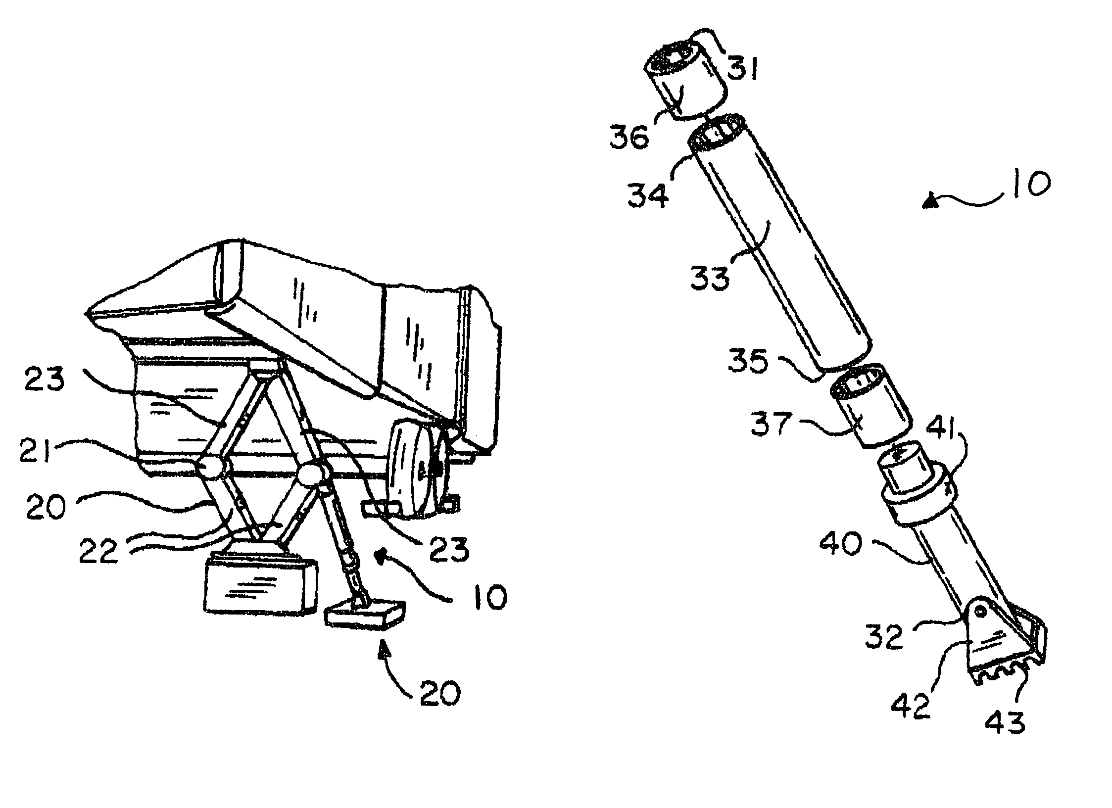
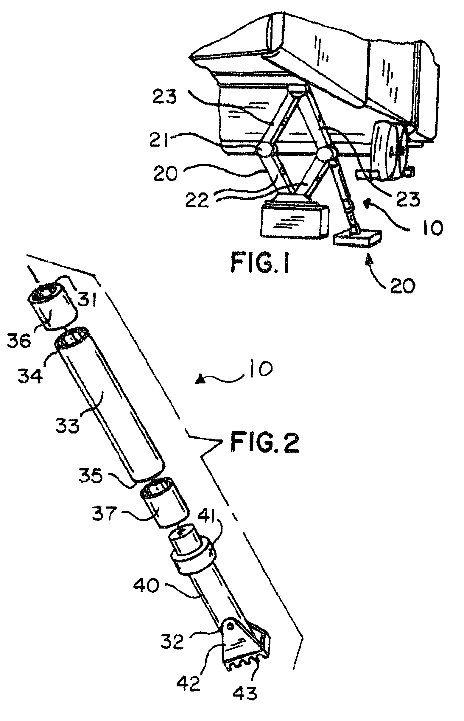
[0011]In view of the foregoing background, it is therefore an object of the present invention to provide an apparatus for stabilizing 5th wheel and traveling trailers. These and other objects, features, and advantages of the invention are provided by a rod for supporting a scissor jack commonly used to stabilize 5th wheel and traveling trailers during non-operating conditions. It should be noted that the present invention can be adapted to support various sized scissors jacks commonly employed for exerting pressure and supporting a selected end portion of 5th wheel and traveling trailers a short distance above a ground surface.

Problems solved by technology

While such suspension systems enhance passenger comfort and minimize vibration, they often detract from the stability of the passenger compartment when the vehicle is parked.
For example, when passengers move about the compartment, the vehicle tends to rock both fore and aft as well as from side to side.
Difficulties with conventional stabilizer jack devices proposed heretofore have been encountered in installed applications where the lateral flanges of the mounting channel and strut would spread laterally outwardly allowing the drive screw and strut to become racked and unbalanced in loading.
This spreading of the upwardly turned flanges of the strut results in failure when the flanges slip off of the axle tabs.
Although these angular support members increase longitudinal stability, the additional components increase manufacturing costs, assembly time and complexity.

Method used


Image

  • Support rod for stabilizing an existing scissor jack
  • Support rod for stabilizing an existing scissor jack

Examples


Embodiment Construction

[0020]The present invention will now be described more fully hereinafter with reference to the accompanying drawings, in which a preferred embodiment of the invention is shown. This invention may, however, be embodied in many different forms and should not be construed as limited to the embodiment set forth herein. Rather, this embodiment is provided so that this application will be thorough and complete, and will fully convey the true scope of the invention to those skilled in the art. Like numbers refer to like elements throughout the figures.

[0021]The apparatus of this invention is referred to generally in FIGS. 1–2 by the reference numeral 10 and is intended to provide a support rod 10 for stabilizing a conventional scissor jack 20. It should be understood that the support rod 10 is not intended to lift the full weight of any RV or similar vehicle. Its use is only to support the existing scissor jack 20 to eliminate the inherent side-to-side movement thereof during operating con...


PUM


Abstract

A support rod that is engageable with the bottom surface of an existing scissor jack. The rod includes an adjustable top portion selectively movable between raised and lowered positions. An elongated and portable support rod is removably engageable with the jack. The rod is provided with axially opposed end portions wherein one end portion has a bored surface for contacting the jack and another end portion is supported on the ground surface. The rod further includes a leg portion removably securable to another coupling that includes a compression-type fitting for adjusting a length of the rod. The leg portion further includes a shoe pivotally attached to a lower end portion thereof and for assisting to maintain the rod at a substantially stable position. A second rod should be symmetrically positioned opposite the first rod and against a second scissor jack on the opposite side of the vehicle, for providing necessary support.

Description

CROSS REFERENCE TO RELATED APPLICATIONS[0001]Not Applicable.STATEMENT REGARDING FEDERALLY SPONSORED RESEARCH OR DEVELOPMENT[0002]Not Applicable.REFERENCE TO A MICROFICHE APPENDIX[0003]Not Applicable.BACKGROUND OF THE INVENTION[0004]1. Technical Field[0005]This invention relates to jack supporting devices and, more particularly, to a support rod for stabilizing a scissor jack employed by 5th wheel and travel trailers.[0006]2. Prior Art[0007]Recreational vehicles and trailers typically incorporate spring suspension systems mounted between the chassis frame and the wheels to provide a smooth ride during transit. While such suspension systems enhance passenger comfort and minimize vibration, they often detract from the stability of the passenger compartment when the vehicle is parked. For example, when passengers move about the compartment, the vehicle tends to rock both fore and aft as well as from side to side. Furthermore, this rocking motion is enhanced due to the inherent flexibili...

Claims


Application Information

Patent Timeline
Patent Type & Authority Patents(United States)
IPC IPC(8): A47F5/00
CPCB66F3/12
Inventor TROUT, KENNETH R.
Owner TROUT KENNETH R
Why Eureka
Try Eureka