
Blow molded side panel chair system

a side panel and seat technology, applied in the field of blow molding side panel chair system, can solve the problems of minimizing cost and weight, and achieve the effects of low manufacturing cost, convenient and efficient manufacturing and marketing, and durable and reliable construction

Active Publication Date: 2006-07-04
WINCO MFG
View PDF9 Cites 7 Cited by
  • Summary
  • Abstract
  • Description
  • Claims
  • Application Information

AI Technical Summary

Benefits of technology

[0016]Further provided is a pair of panels. The panels are blow molded from an elastomeric material. The elastomeric material is selected from the class of elastomers. The class of elastomers includes plastic and rubber, natural and synthetic, and blends thereof. The material is preferably polyethylene. The pair of panels includes one panel for each tubular support. Each panel has an interior vertical wall. The interior vertical wall is adjacent to the seat. A laterally spaced exterior wall is provided next. The exterior wall is remote from the seat. A periphery is provided between the interior and exterior walls. Each periphery has a concave profile. The concave profile receives the vertical sections and intermediate section of an adjacent tubular support. A horizontal profile is provided beneath the intermediate section. An arcuate recess is provided. The arcuate recess is provided adjacent to the forward vertical support and the horizontal support. The exterior wall of the side panel has a continuous recess. The continuous recess is congruent with the periphery of its panel. The continuous recess extends toward the interior wall. The interior wall of the side panel has a discontinuous recess. An inverted U-shaped component is provided. The inverted U-shaped component extends above the seat panel. A horizontal component is provided. The horizontal component is provided below the seat panel. The horizontal component extends toward the exterior wall. In this manner the safety, strength and durability of the system are maximized while minimizing its cost and weight. Each panel includes an elongated extension. The elongated extension extends downwardly from the entire length of the interior wall. Each panel includes a shortened extension. The shortened extension extends upwardly from the interior wall between a portion of the leading and intermediate sections of its frame.
[0021]It is therefore an object of the present invention to provide a new and improved blow molded side panel chair system which has all of the advantages of the prior art chairs of known designs and configurations and none of the disadvantages.
[0022]It is another object of the present invention to provide a new and improved blow molded side panel chair system which may be easily and efficiently manufactured and marketed.
[0023]It is further object of the present invention to provide a new and improved blow molded side panel chair system which is of durable and reliable constructions.
[0024]An even further object of the present invention is to provide a new and improved blow molded side panel chair system which is susceptible of a low cost of manufacture with regard to both materials and labor, and which accordingly is then susceptible of low prices of sale to the consuming public, thereby making such blow molded side panel chair system economically available to the buying public.
[0025]Even still another object of the present invention is to provide a blow molded side panel chair system for maximizing the safety, strength and durability of a chair system while minimizing its cost and weight.

Problems solved by technology

While these devices fulfill their respective, particular objectives and requirements, the aforementioned patents do not describe a blow molded side panel chair system that allows maximizing the safety, strength and durability of a chair system while minimizing its cost and weight.

Method used


Image

  • Blow molded side panel chair system
  • Blow molded side panel chair system
  • Blow molded side panel chair system

Examples


Embodiment Construction

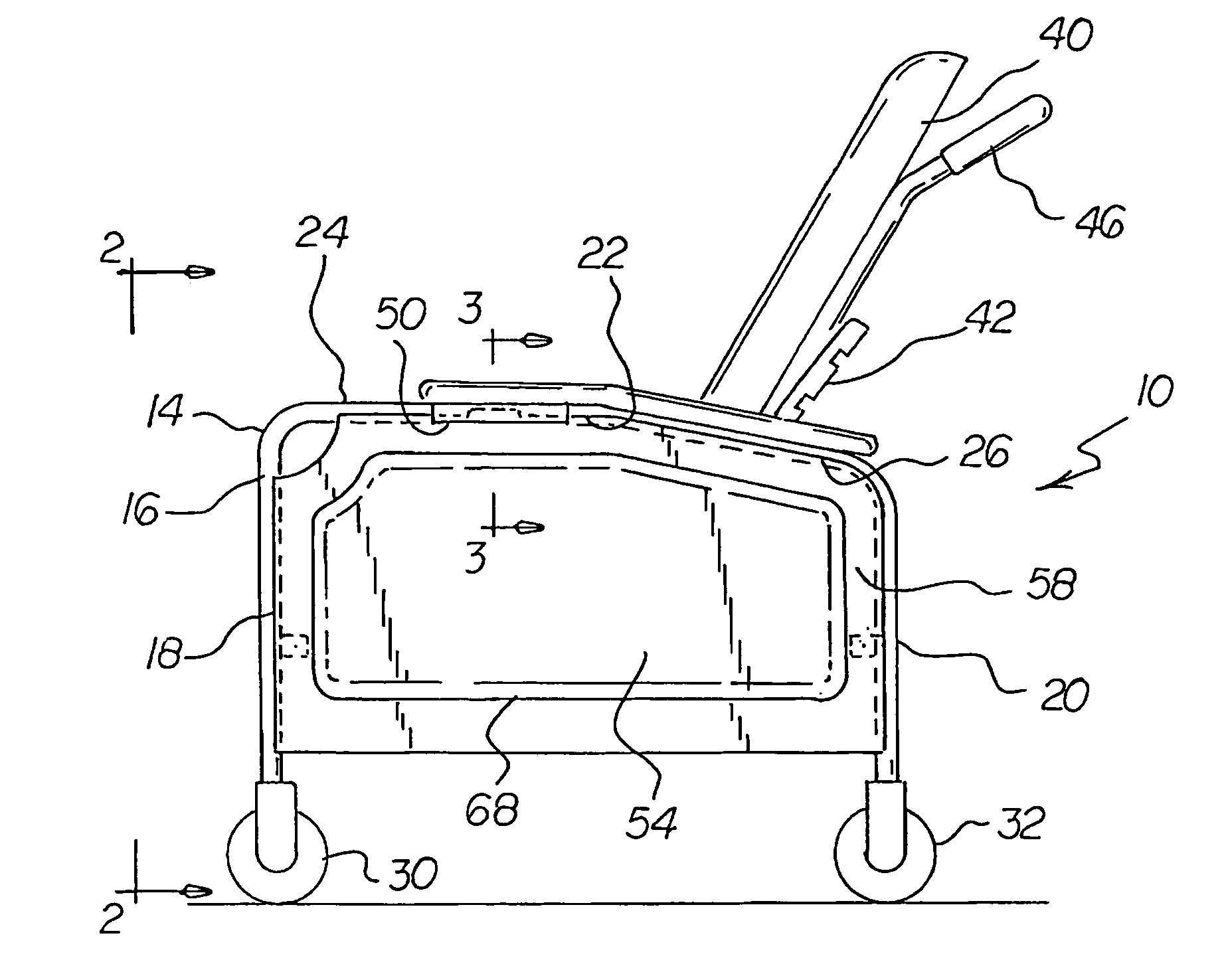
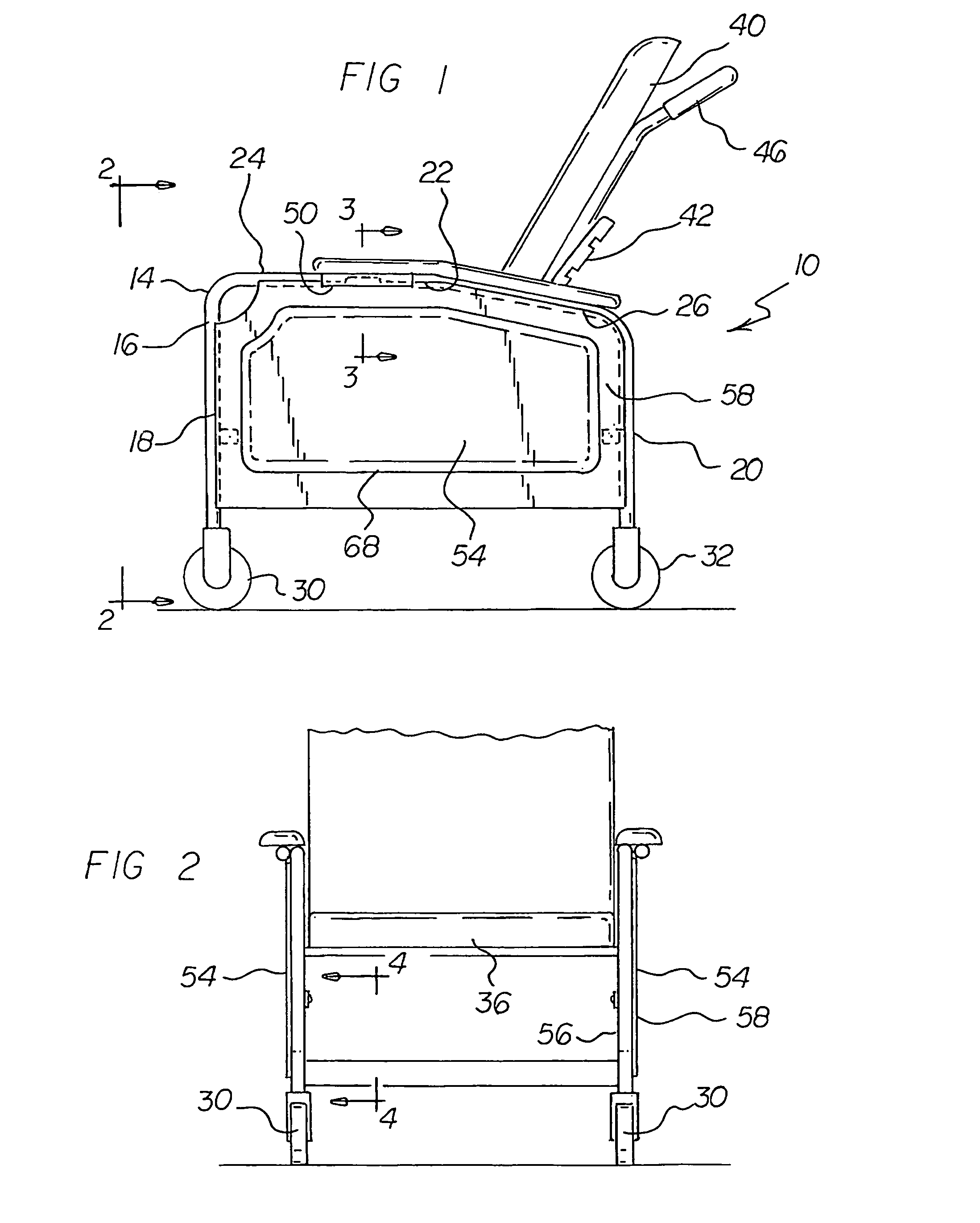
[0036]With reference now to the drawings, and in particular to FIG. 1 thereof, the preferred embodiment of the new and improved blow molded side panel chair system embodying the principles and concepts of the present invention and generally designated by the reference numeral 10 will be described.

[0037]The present invention, the blow molded side panel chair system 10 is comprised of a plurality of components. Such components in their broadest context include a frame, a seat panel, a back panel and a pair of side panels. Such components are individually configured and correlated with respect to each other so as to attain the desired objective.

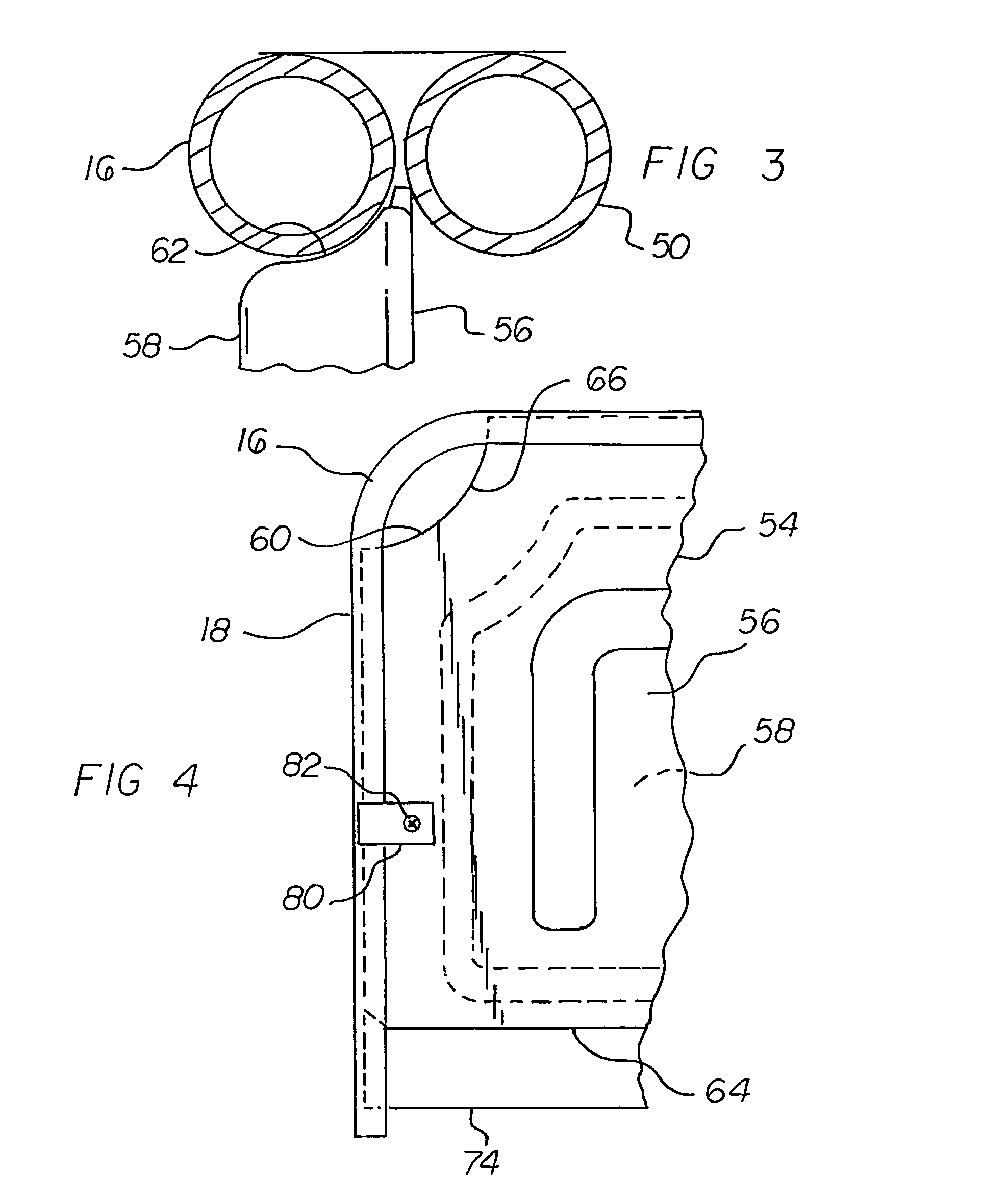
[0038]First provided is a metallic frame 14. The metallic frame has a pair of laterally spaced tubular supports 16. The supports are in a generally inverted U-shaped configuration. Each support has a forward vertical section 18. The forward vertical section has a lower end. Each support has a rearward vertical section 20. The rearward vertical s...


PUM

PropertyMeasurementUnit
strengthaaaaaaaaaa
durabilityaaaaaaaaaa
lengthaaaaaaaaaa

Abstract

A frame has a pair of laterally spaced tubular supports in a generally inverted U-shaped configuration. A seat panel, in a generally horizontal plane, is secured between the supports. A back panel is supported by the seat panel. A pair of side panels includes one panel coupled to each tubular support. Each panel has an interior wall and an exterior wall. A periphery is provided between the walls. Each exterior wall has a continuous recess congruent with its periphery. The interior wall of each side panel has a discontinuous recess. An inverted U-shaped component extends above the seat panel and a horizontal component is below the seat panel.

Description

BACKGROUND OF THE INVENTION[0001]1. Field of the Invention[0002]The present invention relates to a blow molded side panel chair system and more particularly pertains to maximizing the safety, strength and durability of a chair system while minimizing its cost and weight.[0003]2. Description of the Prior Art[0004]The use of chairs of known designs and configurations is known in the prior art. More specifically, chairs of known designs and configurations previously devised and utilized for the purpose of fabricating chairs by conventional methods and apparatuses are known to consist basically of familiar, expected, and obvious structural configurations, notwithstanding the myriad of designs encompassed by the crowded prior art which has been developed for the fulfillment of countless objectives and requirements.[0005]By way of example, U.S. Pat. No. 6,666,505 issued Dec. 23, 2003 to Greger relates to a reclining child seat and U.S. Pat. No. 4,854,638 issued Aug. 8, 1889 to Marcus rela...

Claims


Application Information

Patent Timeline
Patent Type & Authority Patents(United States)
IPC IPC(8): A47C7/02
CPCA47C5/12
Inventor FRANK, DONALD R.
Owner WINCO MFG
Learn More