
Catheter distal assembly with pull wires

a technology of catheter and distal assembly, which is applied in the field of medical surgical instruments, can solve problems such as making tasks more difficult, and achieve the effect of safe and easy introduction

Inactive Publication Date: 2006-06-20
EP TECH
View PDF76 Cites 276 Cited by
  • Summary
  • Abstract
  • Description
  • Claims
  • Application Information

AI Technical Summary

Benefits of technology

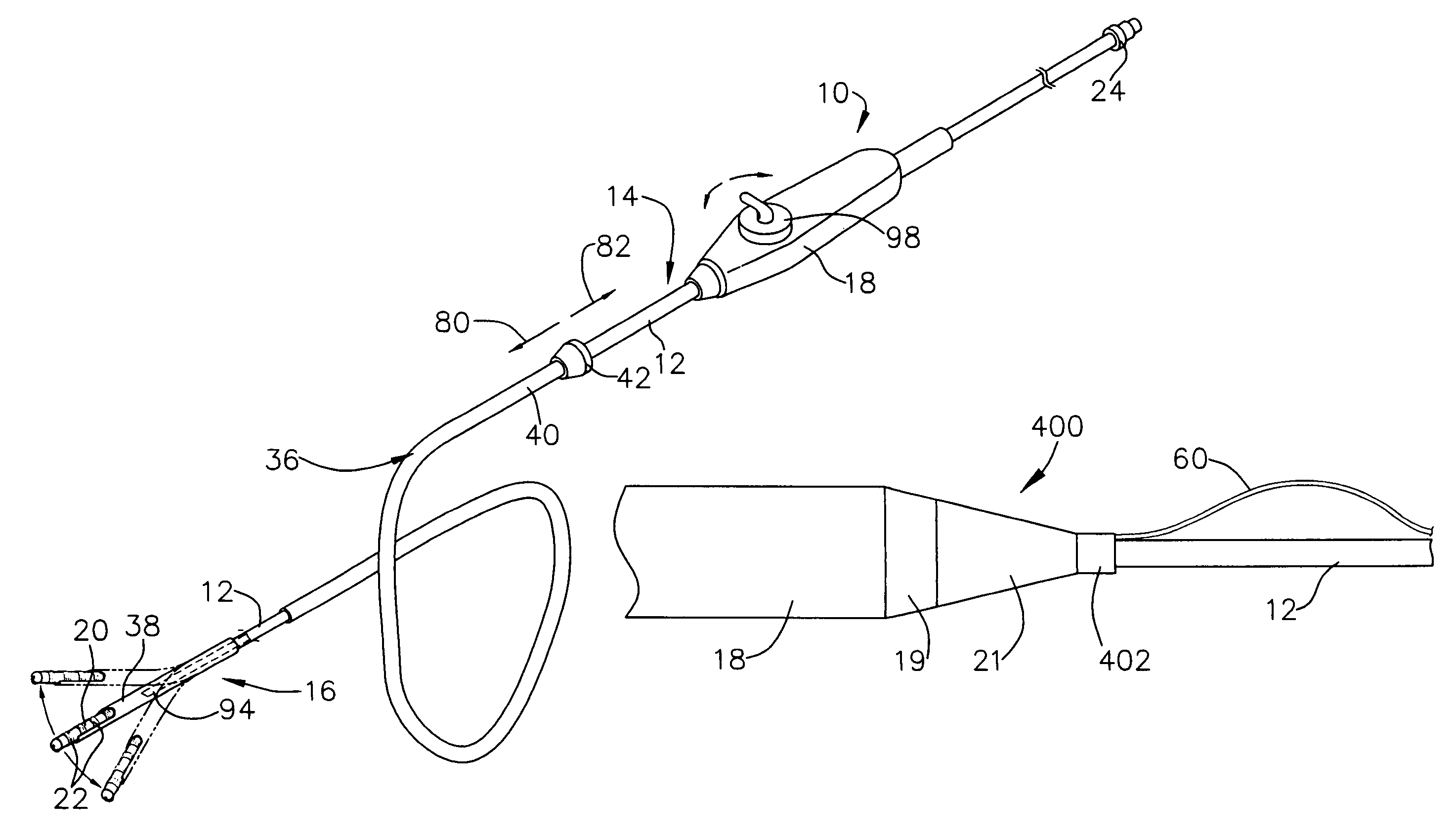
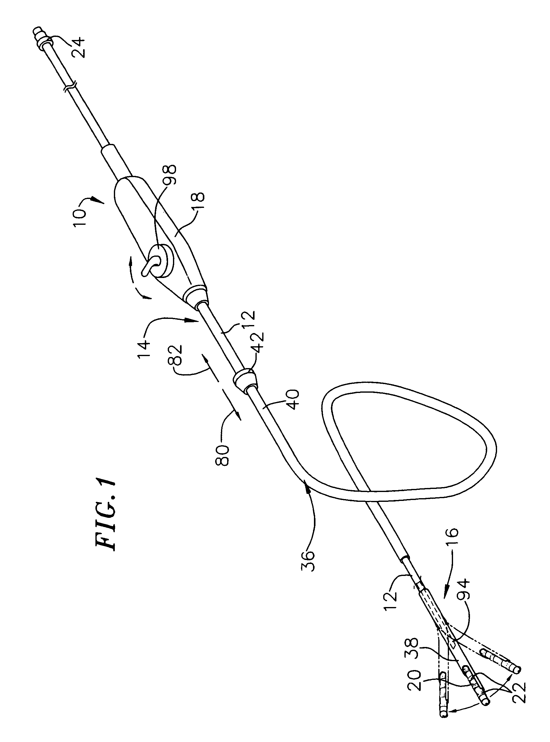
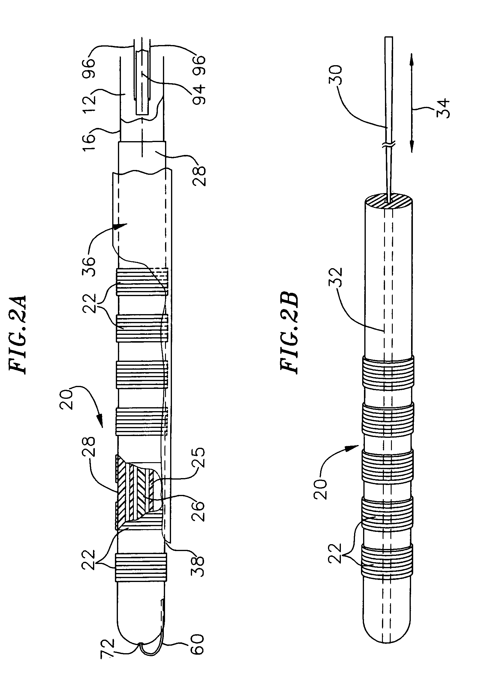
[0009]The invention provides structures for supporting operative therapeutic or diagnostic elements within an interior body region, like the heart. The structures possess the requisite flexibility and maneuverability permitting safe and easy introduction into the body region. Once deployed in the body region, the structures possess the capability to exert force against tissue thereby deforming the tissue resulting in conformance between tissue and elements.
[0011]There are many advantages associated with this embodiment of the present invention. For example, this embodiment is more compact than conventional probes. Additionally, the relatively flexible control element is less likely to cause tissue damage than the control elements in conventional probes.
[0013]There are many advantages associated with this embodiment of the present invention. For example, the control element, which is typically a pull wire, is less likely to wrap around the catheter body than is the control element in a conventional device. As a result, when the present assembly is used in conjunction with a sheath, the catheter is less likely to become stuck within the sheath.
[0015]There are many advantages associated with this embodiment of the present invention. For example, the second cross-sectional shape may be a relatively flat shape. As compared to conventional probe assemblies, the flat shape provides increased predictability and consistency in the deflection direction of the elongate body and, therefore, better control of the movement of the elongate body. This is especially true when the elongate body is used to form loops.

Problems solved by technology

The task is made more difficult because heart chambers vary in size from individual to individual.

Method used


Image

  • Catheter distal assembly with pull wires
  • Catheter distal assembly with pull wires
  • Catheter distal assembly with pull wires

Examples


Embodiment Construction

[0068]The following is a detailed description of the best presently known mode of carrying out the invention. This description is not to be taken in a limiting sense, but is made merely for the purpose of illustrating the general principles of the invention. The scope of the invention is defined solely by the appended claims.

[0069]This Specification discloses various multiple electrode structures in the context of catheter-based cardiac ablation. That is because the structures are well suited for use in the field of cardiac ablation. Still, it should be appreciated that the disclosed structures are applicable for use in other applications. For example, the various aspects of the invention have application in procedures requiring access to other regions of the body, such as, for example, the prostate, brain, gall bladder, and uterus. The structures are also adaptable for use with systems that are not necessarily catheter-based.

[0070]The detailed description of the preferred embodimen...


PUM


Abstract

A catheter assembly having a sheath, which includes a side wall enclosing an interior bore, and a distal region. The assembly also has a bendable catheter tube, which is carried for sliding movement in the interior bore. A pull wire also runs through the interior bore of the sheath, preferably within a lumen. The catheter tube has a distal portion with a coupling which joins the distal portion of the catheter tube and the distal portion of the pull wire. Relative movement of the pull wire and the sheath causes bending of the catheter tube outwardly through the opening, in response to sliding movement of the catheter tube within the interior bore toward the distal region of the sheath.

Description

CROSS-REFERENCE TO RELATED APPLICATIONS[0001]This application is a continuation of U.S. application Ser. No. 08 / 961,374, filed Oct. 30, 1997, now U.S. Pat. No. 6,203,525, which is a continuation-in-part of U.S. application Ser. No. 08 / 769,856, filed Dec. 19, 1996, now U.S. Pat. No. 6,332,880, which is incorporated herein by reference thereto.BACKGROUND OF THE INVENTION[0002]1. Field of Invention[0003]The invention generally relates to the field of medical surgical instruments, specifically structures for supporting one or more diagnostic or therapeutic elements in contact with body tissue. In a more particular sense, the invention relates to structures well suited for supporting one or more electrode elements within the heart.[0004]2. Description of the Related Art[0005]There are many instances where diagnostic and therapeutic elements must be inserted into the body. One instance involves the treatment of cardiac conditions such as atrial fibrillation and atrial flutter which lead t...

Claims


Application Information

Patent Timeline
IPC IPC(8): A61M37/00A61B18/14A61M25/00A61M25/01
CPCA61B18/1492A61M25/0043A61M25/01A61M25/0144A61M25/0147A61M25/0152A61B2017/00867A61B2018/00553A61B2018/00577A61B2018/00797A61B2018/1407A61B2018/142A61B2018/1467A61B2018/1861A61M2025/015A61M2025/0163C08L2201/12A61B2018/00065
Inventor WHAYNE, JAMES G.FLEISCHMAN, SIDNEY D.
Owner EP TECH
Learn More