
Displaying control points over a timeline

a control point and timeline technology, applied in the field of image data processing apparatus, can solve the problems of timelines or editing, interfaces for known effects processing, and differences in known interfaces

Active Publication Date: 2006-06-13
AUTODESK INC
View PDF18 Cites 49 Cited by
  • Summary
  • Abstract
  • Description
  • Claims
  • Application Information

AI Technical Summary

Benefits of technology

[0016]According to an aspect of the present invention, there is provided Image data processing apparatus, comprising frame storage means, processing means, manually operable input means and display means, wherein said display means is configured to display: (a) a first region representing a first timeline showing transitions between a first set of clips; (b) a second region representi

Problems solved by technology

Problems therefore arise in that if an editor wishes to modify an effect it is necessary for the material to be processed again within an effects environment and then exported back to the editing environment.
Alternatively, editors could be presented with effects functionality, but a problem occurs in that interfaces for known effects processing differs substantially from known interfaces, including timelines or editing.

Method used


Image

  • Displaying control points over a timeline
  • Displaying control points over a timeline
  • Displaying control points over a timeline

Examples


Embodiment Construction

FIG. 1

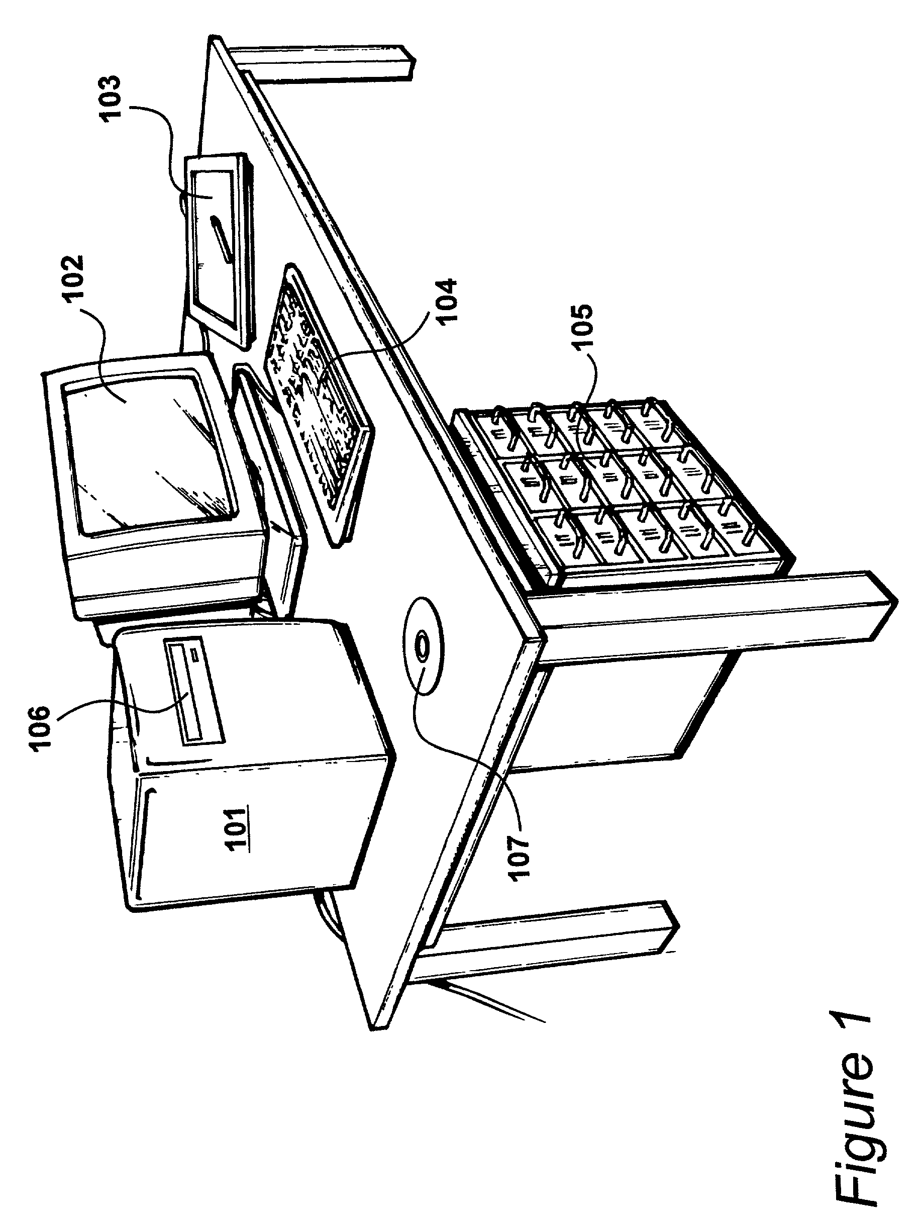
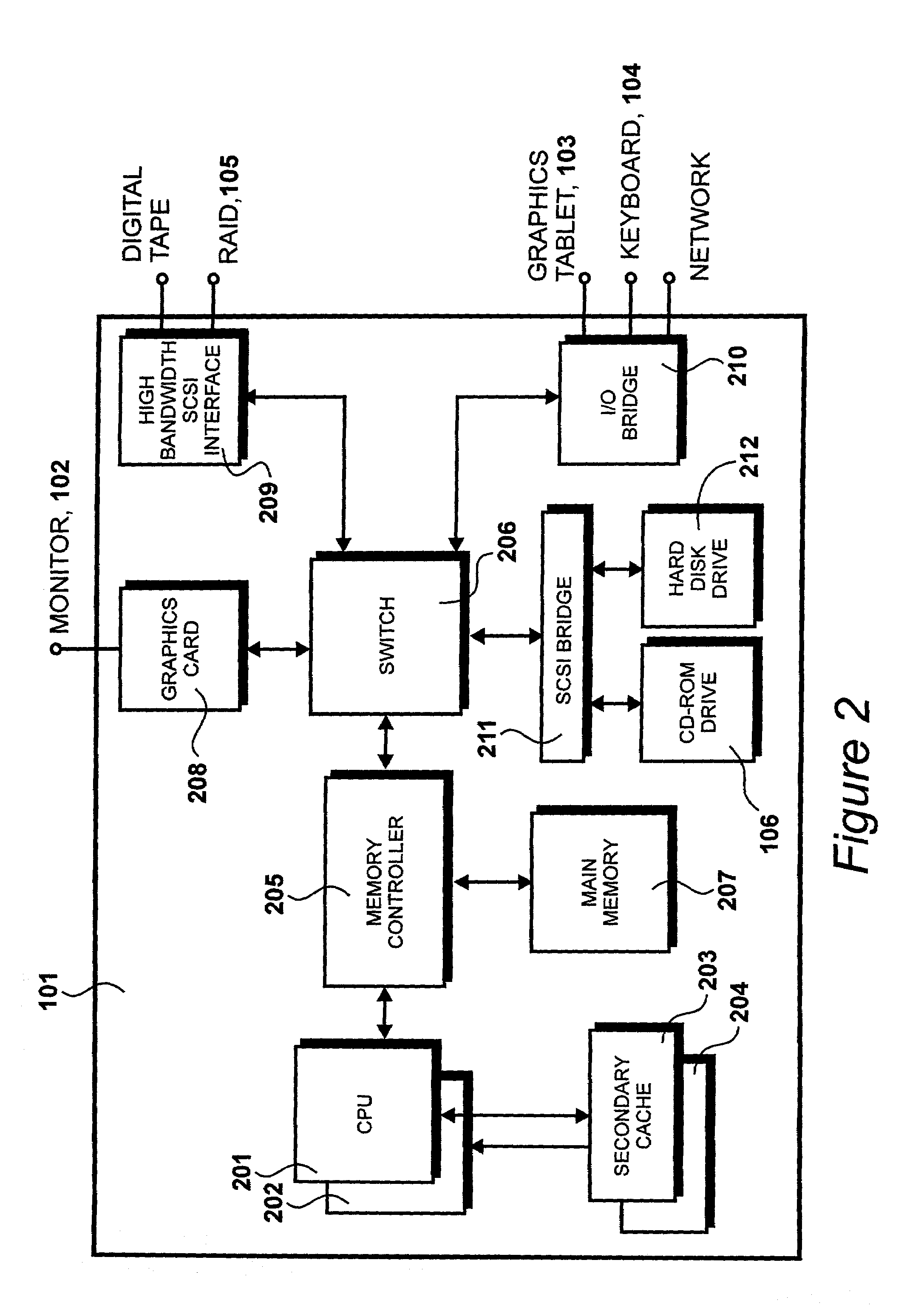
[0027]A system for editing image data and for controlling effects processing is illustrated in FIG. 1. The system includes a computer 101 configured to display video output via a monitor 102. The computer runs applications software that facilitates the editing and processing operations and monitor 102 provides a graphical user interface to a user, allowing film or video clips to be previewed and facilitating the control of editing and effects manipulation.

[0028]The graphical user interface provides a user with several controls and interfaces for controlling the manipulation of image data. The system also includes a graphics tablet 103, to allow the user to interact with a graphical user interface and a keyboard 104 to facilitate alpha numeric input.

[0029]The system further comprises a disk based frame storage system 105, referred to herein as a Framestore. In preparation for image editing and manipulation, images from one or more film or video input reels are transferred to th...


PUM


Abstract

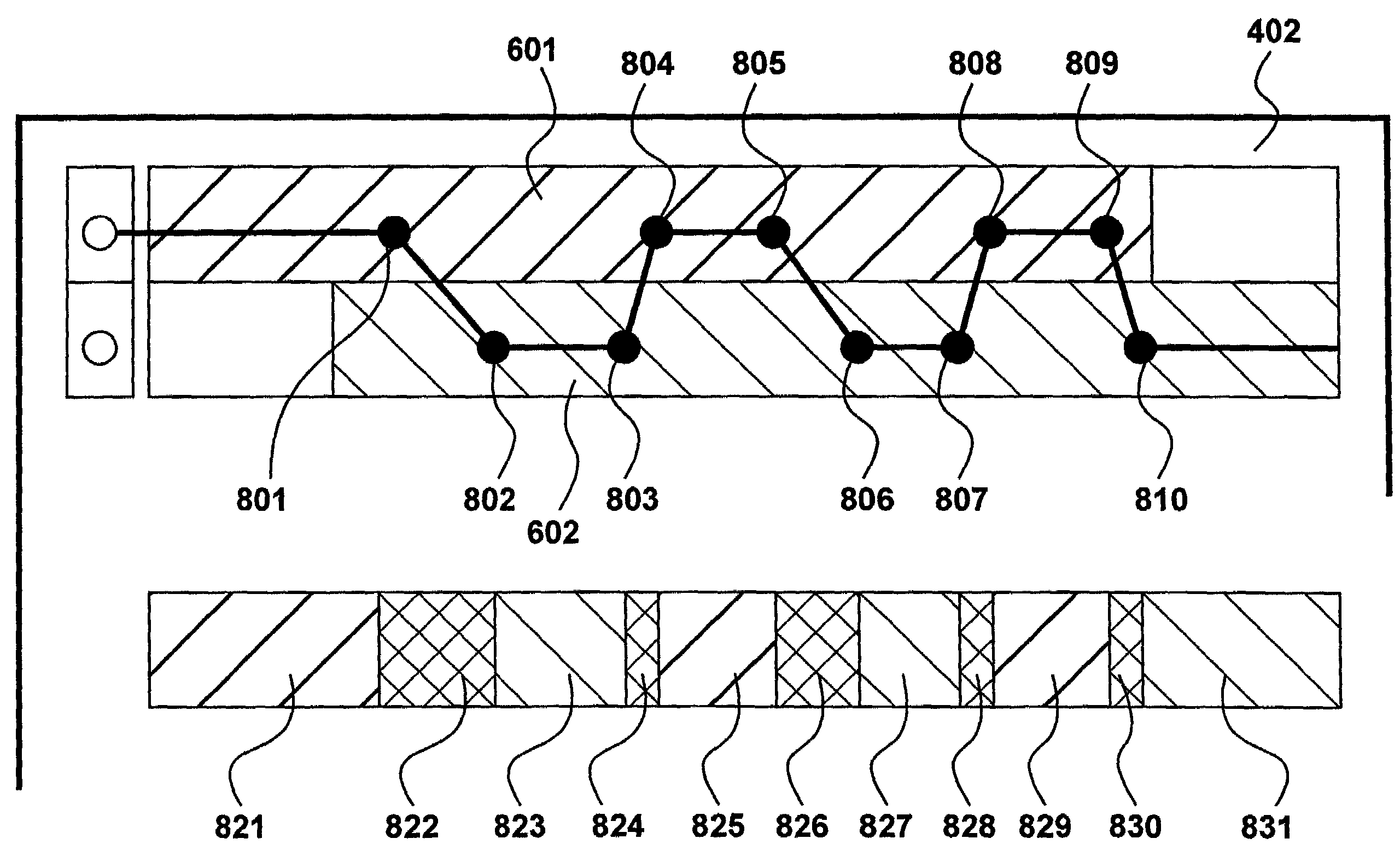
On a display monitor (102) the first region is displayed representing a first timeline (601) showing transitions between a first set of image clips. A second region is displayed representing a second timeline (602) showing transitions between a second set of image clips. Control points (621,622) are displayed over said first timeline (601) and over second timeline (602). The location of the control points controls an effect upon a first clip (601) and upon a second clip (602).

Description

CROSS-REFERENCE TO RELATED APPLICATIONS[0001]This application claims priority under 35 USC § 119 to the following co-pending and commonly-assigned patent application which is incorporated by reference herein:[0002]United Kingdom Patent Application Number 01 09 740.1, entitled “IMAGE DATA PROCESSING”, filed on Apr. 20, 2001.[0003]This application is related to the following co-pending and commonly-assigned patent(s) and / or patent application(s), which are incorporated by reference herein:[0004]U.S. Pat. No. 5,818,542, entitled “PROCESSING IMAGE DATA”, by Stephane Robert Harnois, Attorney Docket No. 30566.152US01, issued on Oct. 6, 1998 (Application Ser. No. 632,341, filed on Apr. 10, 1996);[0005]U.S. Pat. No. 6,269,180, entitled “METHOD AND APPARATUS FOR COMPOSITING IMAGES”, by Benoit Sevigny, Attorney Docket No. 30566.180US01, issued on Jul. 31, 2001 (application Ser. No. 08 / 827,641 filed on Apr. 9, 1997), which is based on British Patent No. 2312124 filed on Apr. 12, 1996;[0006]U.S...

Claims


Application Information

Patent Timeline
IPC IPC(8): G11B27/00G11B27/034G11B27/34
CPCG11B27/034G11B27/34G11B2220/90G11B2220/415
Inventor SCHRIEVER, MICHIELROBERTS, WILLIAM JAMES
Owner AUTODESK INC
Learn More