
Techniques for sample rate conversion

a sample rate and sample technology, applied in the field of digital systems, can solve the problem of far more problematic irrational decimation

Active Publication Date: 2006-06-13
NOKIA TECHNOLOGLES OY
View PDF2 Cites 61 Cited by
  • Summary
  • Abstract
  • Description
  • Claims
  • Application Information

AI Technical Summary

Benefits of technology

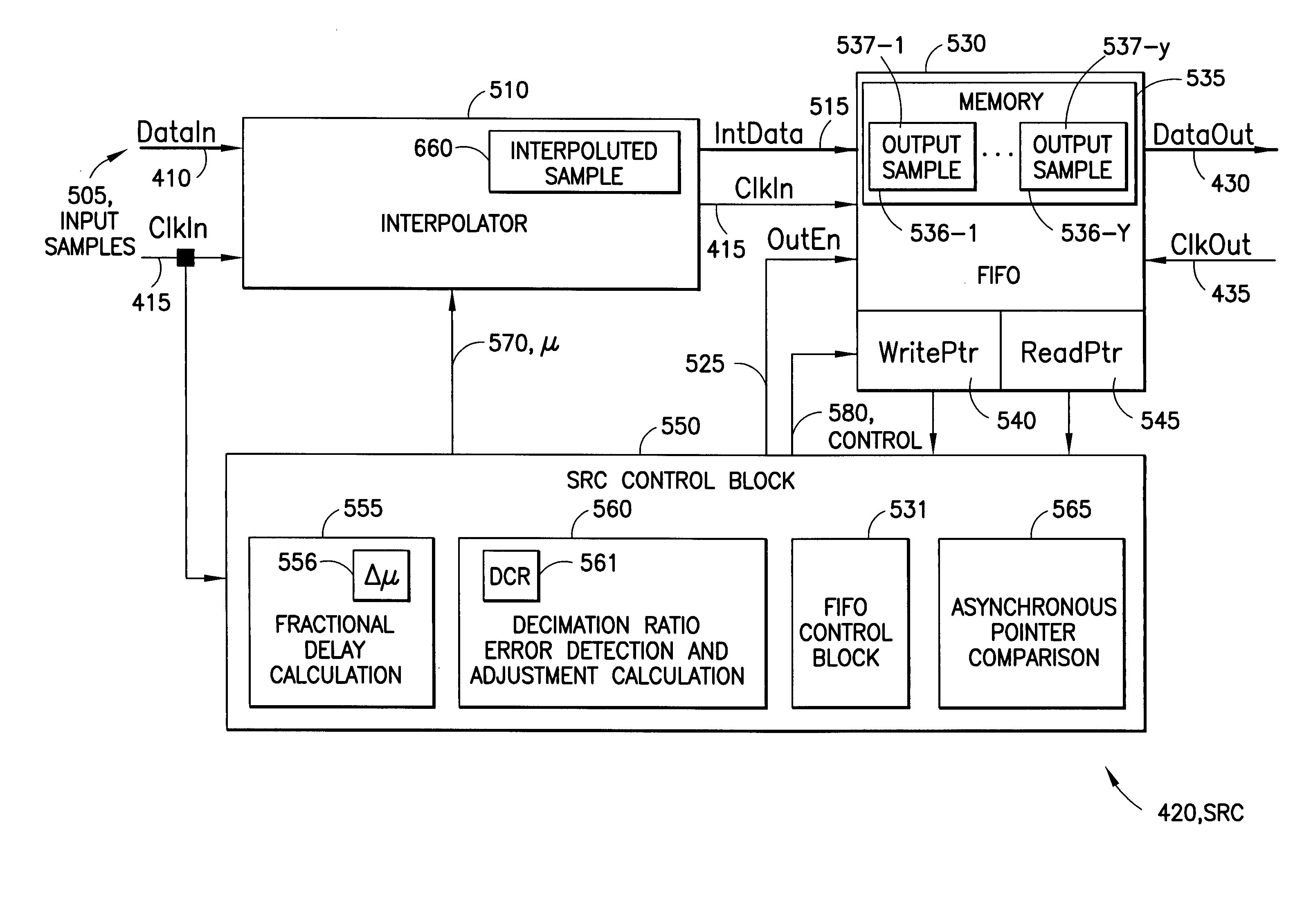
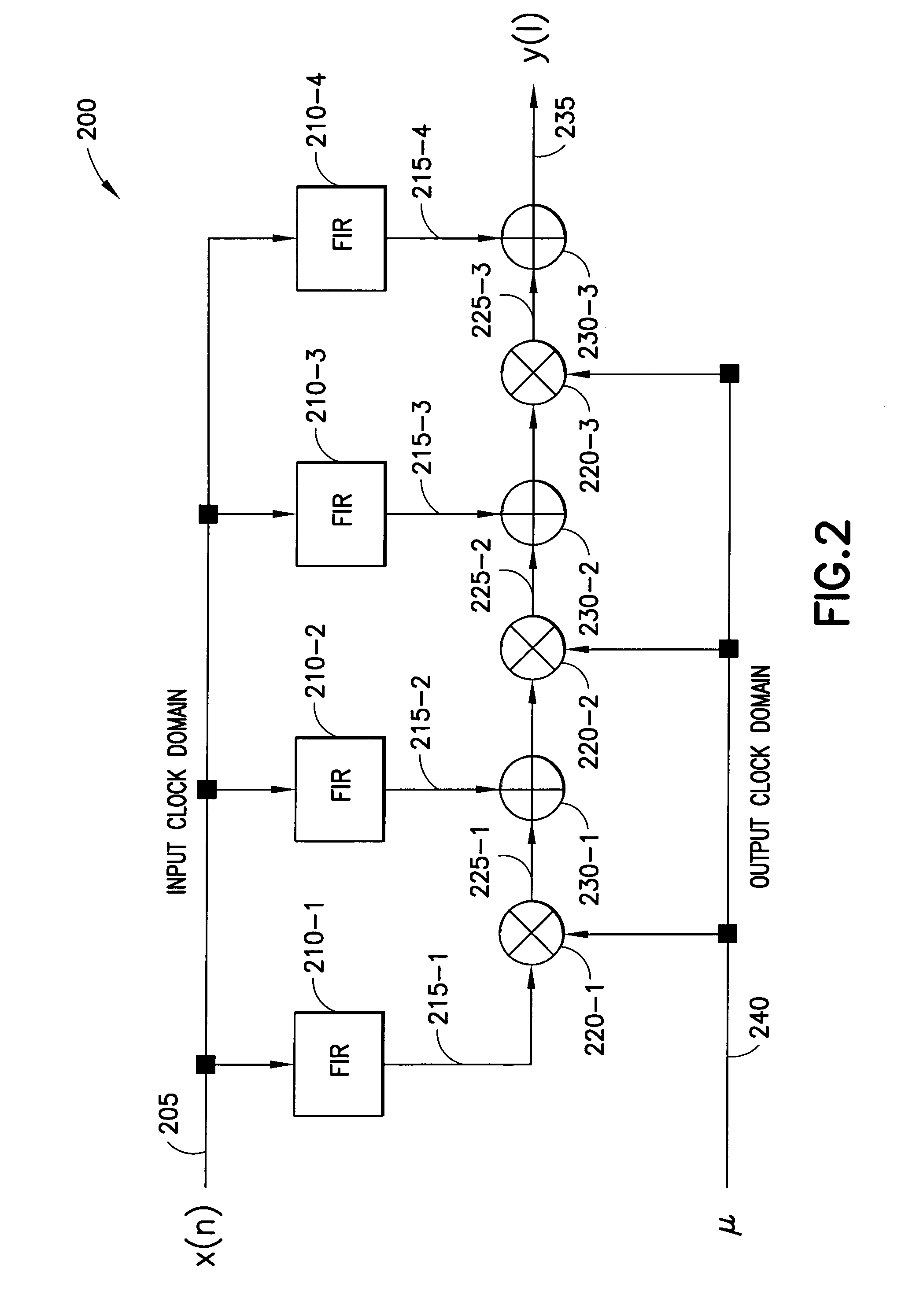
The present invention provides techniques for sample rate conversion between first and second samples having different sample rates. These techniques can be used for both rational and irrational conversion ratios, including decimation ratios. The invention also includes an adaptive conversion ratio tracking method that can support arbitrary ratios. The sample rate converter can be used as an interface element between two blocks having different sample rates. The technical effects of the invention include improved sample rate conversion and improved adaptive conversion ratio tracking.

Problems solved by technology

Irrational decimation is far more problematic, because there are no exact signal values available for each second sample and new second samples need to be interpolated between existing first samples.
While there are techniques to perform irrational decimation, many of these techniques have certain problems, e.g., an exact conversion ratio needs to be set beforehand.

Method used


Image

  • Techniques for sample rate conversion
  • Techniques for sample rate conversion
  • Techniques for sample rate conversion

Examples


Embodiment Construction

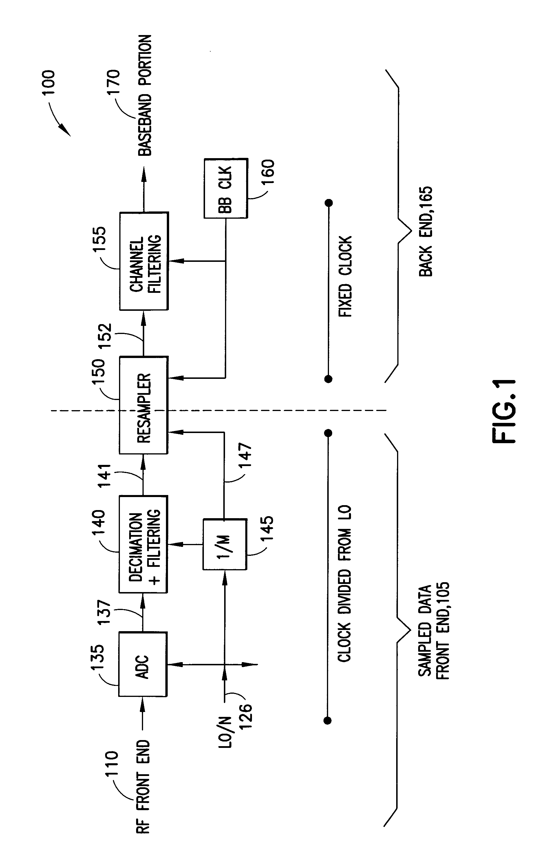
[0026]As previously described, decimation is used when a first clock frequency for a first portion of a digital system is higher than a second clock frequency for the second portion of the digital system, and when samples are to be passed from the first to the second portion. Typically, a conversion ratio that defines a relationship between the first and second clock signals is used when determining second samples. The relationship is based on frequencies of the first and second clock signals. Thus, a conversion ratio of 2.0 means that the frequency of the first clock signal is twice the frequency of the second clock signal. The relationship, however, may be any based on other clock information such as period.

[0027]A use for sample rate conversion is typically in communications, where the digital system is a receiver, and there are at least two different use cases for rational and irrational decimation in a receiver. The first and most observable use case of sample rate conversion i...


PUM


Abstract

Techniques for sample rate conversion are disclosed. In one exemplary embodiment, a sample rate conversion occurs between first samples having a sample rate defined by a first clock signal and second samples having a sample rate defined by a second clock signal. Using a conversion ratio and at a first rate defined by the first clock signal, a given second sample is determined from at least one first sample. A write pointer is updated for a buffer when second samples are written into the buffer. A read pointer is updated for the buffer when second samples are read from the buffer. The second samples are read from the buffer at a second rate defined by the second clock signal. The conversion ratio is modified based on the write and read pointers.

Description

TECHNICAL FIELD[0001]This invention relates generally to a digital system using two different clock signals and, more specifically, relates to sample rate conversion between first samples having a sample rate defined by a first clock signal in a first portion of the digital system and second samples having a sample rate defined by a second clock signal in second portion of the digital system.BACKGROUND OF THE INVENTION[0002]In some systems that use digital data, one portion of the digital system operates relative to a first clock signal while a second portion operates relative to a second clock signal. Typically, samples, which are sequences of bits sampled at times regulated by an associated clock signal, are to be passed between the first and second portions of the digital system. When frequencies of the first and second clock signals are different, sample rate conversion is used to convert samples having a sample rate defined by one clock signal into samples having a sample rate ...

Claims


Application Information

Patent Timeline
Patent Type & Authority Patents(United States)
IPC IPC(8): H03M7/00
CPCH03H17/0628H03H17/028
Inventor JANTTI, JONIRUHA, ANTTI
Owner NOKIA TECHNOLOGLES OY
Learn More