
Low deadspace airway adapter

a low-dest space, air-way technology, applied in the direction of adjustable joints, breathing protection, other medical devices, etc., can solve the problems of high sampling rate, high cost of anesthetic agents, and inability to meet the needs of low-tidal volume patients, so as to promote gas flow and minimize the dead space in the airway.

Active Publication Date: 2006-06-13
RIC INVESTMENTS LLC
View PDF16 Cites 44 Cited by
  • Summary
  • Abstract
  • Description
  • Claims
  • Application Information

AI Technical Summary

Benefits of technology

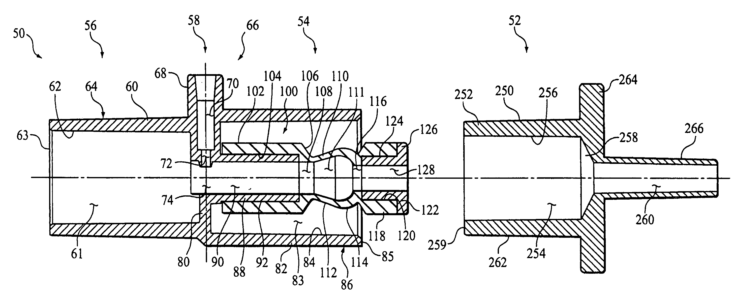
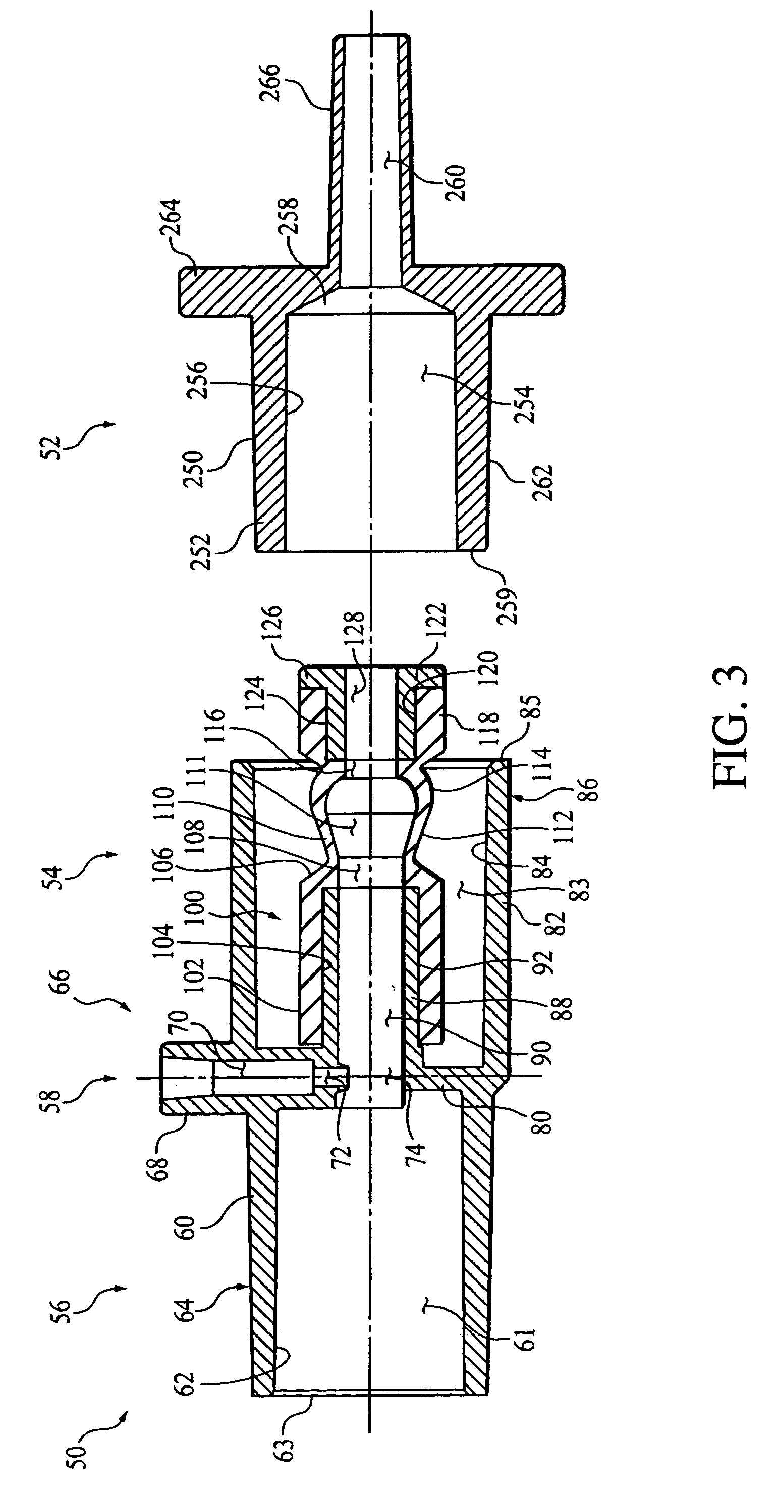
"The present invention provides a sampling airway adapter that is suitable for patients with low tidal volumes, such as neonates, and minimizes deadspace in the airway. The adapter has a compressible member that can be compressed to create a seal with the tubular adapter and allows for smooth flow of gases through the airway. The compressible member can include a pleat to allow for compression or a resilient sleeve that can be compressed without changing the size of the airway passage. The invention reduces deadspace and promotes smooth flow of gases through the airway adapter."

Problems solved by technology

First, the lesser the volume of gas removed from the airway, the lesser the disturbance to the patient's ventilation.
Third, when respiratory assistance is given in the operating room to patients under anesthesia, the sample gas will likely contain anesthetic agents that must be safely vented.
Further, such anesthetic agents are often expensive and should not be wasted.
Such high sampling rates are not viable for low tidal volume patients, due to the unacceptable impact of the high sampling rate on the ventilation of the patient.
With viable low rate sensing mechanisms now available, design challenges for gas sampling systems for use with low tidal volume patients have shifted to providing a system in which a sample can be extracted from the breathing circuit without introducing excessive deadspace, i.e., void volume, into the breathing circuit, adding flow resistance to the breathing circuit, and / or losing the integrity of the sample at the sampling point in the breathing circuit.
There is often a discrepancy between the cross-sectional size of an endotracheal tube and the cross-sectional size of a ventilation tube.
However, termination of the sampling port in the wall of the adapter may permit contaminants and other constituents, which tend to collect along the inner wall of the adapter, to enter the sensing mechanism.
Entry of such contaminants and other constituents into the sensing mechanism is undesired, as it may lead to inaccurate monitoring results.
Internal mixing of respired gases and alterations in the waveform of the gas to be analyzed reduces the accuracy of the gas measurements and, thus, may produce results which do not accurately reflect the patient's medical status.
Consequently, the amount of deadspace produced by the connection of the components and / or airway adapters varies considerably and, for a tight-fitting pair of components, may be of considerable and undesirable magnitude, because, for example, the relatively large amount of deadspace may increase the effects of gas mixing and may result in rebreathing.
Many of the proposed designs, however, are unsuitable for patients in which a very small flow is involved, e.g., neonatal patients, because even a small airway deadspace can cause significant mixing of the neonate's exhaled gases which, again, may produce inaccurate monitoring results.
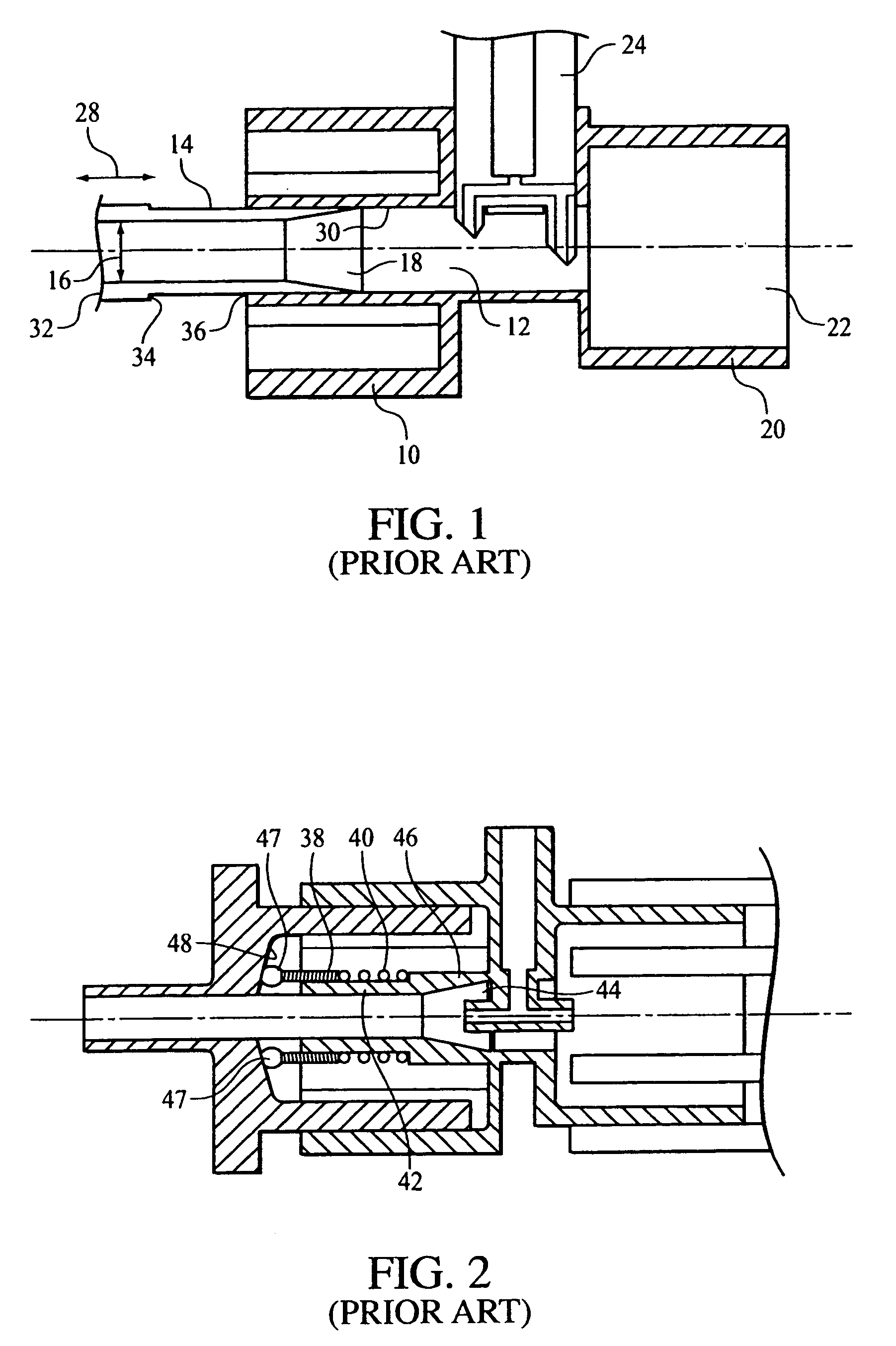
While the two airway adapter embodiments discussed in the '756 application may provide a low volume airway adapter, they may not represent an optimal solution to the problems confronting this technology.
For example, the sliding spring mechanism taught by the embodiments disclosed in the '756 application may become clogged with debris rendering it inoperative.
Furthermore, the adapters taught by the '756 application require multiple parts that may be costly and time consuming to assemble, especially with respect to the sliding mechanism.

Method used


Image

  • Low deadspace airway adapter
  • Low deadspace airway adapter
  • Low deadspace airway adapter

Examples


third embodiment

[0065]FIG. 8 illustrates a sampling airway adapter 300 according to the principles of the present invention. It can be appreciated that this embodiment is structurally similar to that shown in FIGS. 3–6, except for the manner in which a compressible member 302 is attached to a tubular first portion 304 of adapter 300. In this embodiment, a first end portion 306 of compressible member 302 is operatively coupled within first portion 304. As in the previous embodiment, a bore 305 is defined in the compressible member from first end portion 306 to and a second free end portion 308.

[0066]In the illustrated exemplary embodiment of the invention, first end portion 306 of compressible member 302 includes a flange 309 disposed at the first end portion about its periphery. Flange 309 frictionally engages a wall 310 of a bore 312 to maintain the compressible member in place within first portion 304 of the adapter. It is to be understood that other techniques and configurations for attaching th...

fourth embodiment

[0068]FIGS. 9–11 illustrate a sampling airway adapter 400 according to the principles of the present invention. It can be appreciated that this embodiment is structurally similar to that shown in FIGS. 3–6, except for the structure for compressible member 402, which is somewhat similar to that shown in FIG. 7. In the illustrated embodiment, compressible member 402 is attached to a tubular first portion 404 of adapter 400 via a protrusion 406. However, the present invention contemplates attaching compressible member 402 to tubular first portion 404 as shown in FIG. 8. As in the previous embodiments, a bore 408 is defined in the compressible member from first end portion 410 to and a second free end portion 412. Bore 408, in the illustrated embodiment, has an effective flow path diameter that is substantially equal to a bore defined in protrusion 406.

[0069]In the illustrated exemplary embodiment of the invention, first end portion 410 of compressible member 402 is disposed around, and...


PUM


Abstract

An airway adapter suitable for use with patients having low tidal volumes, e.g., neonates, which minimizes deadspace in the airway and promotes smooth flow of gases through the adapter. The adapter includes a first portion adapted to couple to a tubular adapter, such as an endotracheal tube adapter, and a second portion adapted to couple to a ventilation tube. A longitudinally compressible member is coupled to the first portion to minimize deadspace in the adapter. A portion of the compressible member resiliently contacts and seals against a tubular adapter upon assembly of the airway adapter therewith.

Description

CROSS-REFERENCE TO RELATED APPLICATIONS[0001]This application claims priority under 35 U.S.C. § 119(e) from provisional U.S. patent application No. 60 / 417,899 filed Oct. 11, 2002 the contents of which are incorporated herein by reference.BACKGROUND OF THE INVENTION[0002]1. Field of the Invention[0003]The present invention relates generally to an airway adapter for use in connecting an endotracheal tube to a ventilation apparatus, and, in particular, to an airway adapter for use with a sidestream gas monitoring system that minimizes deadspace in the breathing circuit so that it is especially suited for use with a patient having a small endotracheal tube, i.e., an inner diameter of less than approximately 4.0 mm, and commensurately low tidal volumes.[0004]2. Description of the Related Art[0005]During medical treatment, a patient's exhalations are often times monitored and analyzed to determine the gaseous composition thereof. For instance, monitoring of the carbon dioxide (CO2) conten...

Claims


Application Information

Patent Timeline
Patent Type & Authority Patents(United States)
IPC IPC(8): A61M16/00A61M16/04A61M16/08
CPCA61M16/0463A61M16/0816A61M16/085F16L27/11F16L27/12F16L27/108A61M2016/0027A61M2240/00
Inventor RICH, DAVID RTRIUNFO, JR., JOHN ATENCZA, RICHARD SSANDOR, JOHN L
Owner RIC INVESTMENTS LLC
Learn More