
Recording/reproducing apparatus with reduced number of guides posts

Inactive Publication Date: 2006-06-06
CANON KK
View PDF21 Cites 0 Cited by
  • Summary
  • Abstract
  • Description
  • Claims
  • Application Information

AI Technical Summary

Benefits of technology

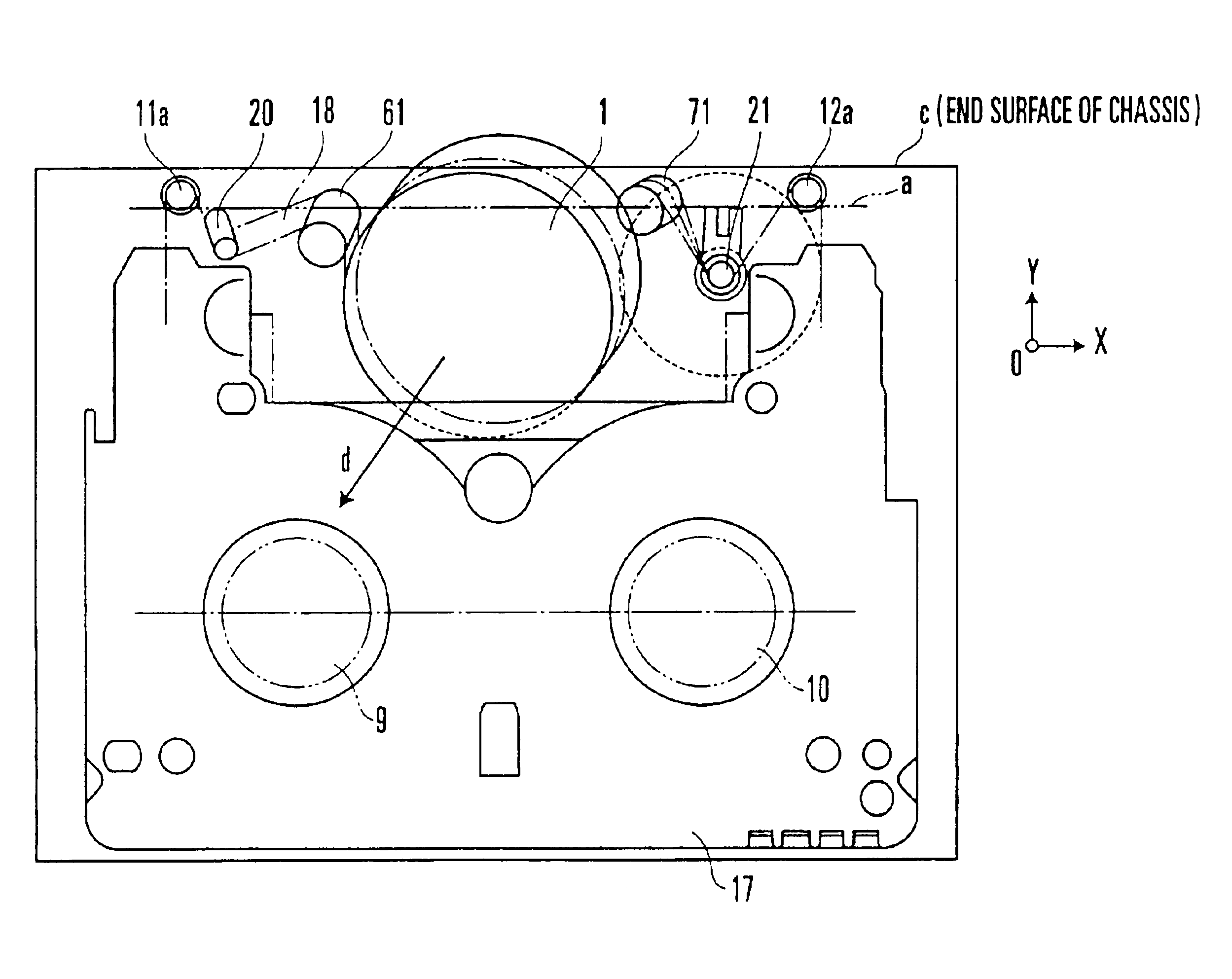
[0013]Under such a background, the invention is directed to the solution of the problems of the prior art described above. It is, therefore, an object of the invention to provide a recording and reproducing apparatus arranged to permit a reduction in size thereof by minimizing a necessary number of the guide posts and by effectively arranging the guide posts at spaces other than spaces occupied by a rotary drum and a tape cassette in a recording or reproducing state, while retaining the predetermined angle of wrapping of a tape around the rotary drum.
[0014]It is another object of the invention to provide a highly-reliable recording and reproducing apparatus which is arranged to have an elastic member allocated and arranged in an improved manner to have guide post bases stably positioned with no rattling.

Problems solved by technology

This method for reduction in size, however, causes an increase in the number of posts to be used, producing a disadvantage in terms of cost, and also lessens the length of recordable time on the tape.
In addition, according to the conventional method for reduction in size, although the size of the rotary drum is decreased to provide additional space, the presence of tape guide members in the space hinders the effective use of the space.
Further, if the guide post bases fail to be correctly positioned with respect to the rotary drum at the tape loading completion positions, the tape wrapping angle and the tape wrapping start and end positions, which determine a signal recording track position on the magnetic tape, cannot be accurately set.
Then, in reproducing a signal from the magnetic tape, track deviations arise to make it hardly possible to retain adequate interchangeability and to retain an adequate rate of positional accuracy with repeated tape loading operations.
However, this arrangement using such an elastic member requires a larger space.

Method used


Image

  • Recording/reproducing apparatus with reduced number of guides posts
  • Recording/reproducing apparatus with reduced number of guides posts
  • Recording/reproducing apparatus with reduced number of guides posts

Examples


Embodiment Construction

[0024]Hereinafter, a preferred embodiment of the invention will be described in detail with reference to the drawings.

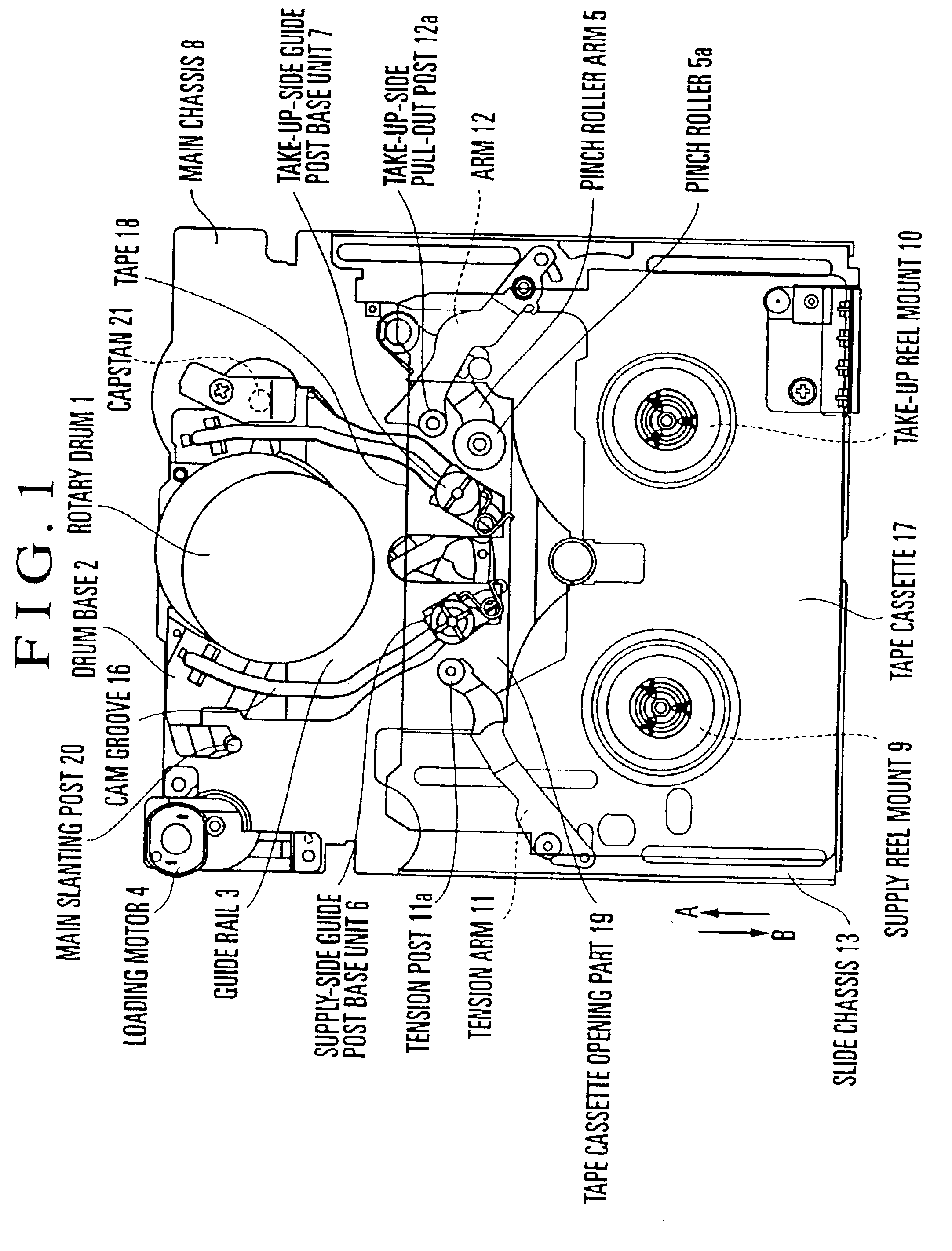
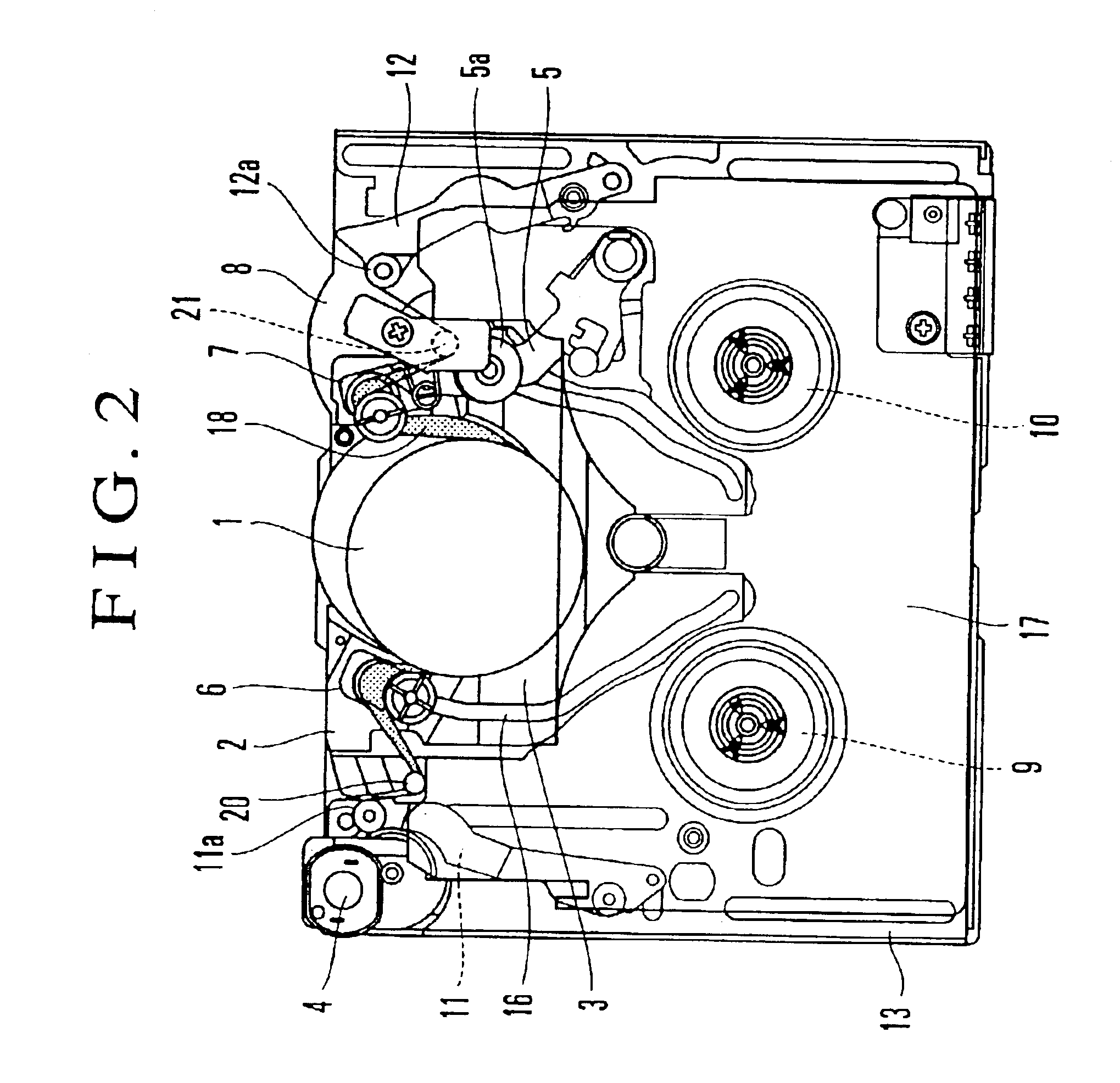
[0025]FIG. 1 is a plan view showing a tape loading apparatus, serving as a recording and reproducing apparatus according to the embodiment of the invention, in a loading standby state. FIG. 2 is a plan view showing the tape loading apparatus, according to the embodiment, in a loading completion state. First, the basic structural arrangement and the operation of the tape loading apparatus according to the embodiment are described below with reference to FIGS. 1 and 2.

[0026]Referring to FIGS. 1 and 2, a rotary drum 1 has magnetic heads (not shown) mounted thereon. A drum base 2 is arranged to support the rotary drum 1. A guide rail 3 has cam grooves 16 formed therein. A loading motor 4 is arranged to serve as a drive source of a tape loading mechanism. A pinch roller 5a is arranged to be pressed against a capstan 21 across a tape, so as to transport the tape. A pinch r...


PUM


Abstract

A recording and reproducing apparatus includes a guide post for pulling out a tape-shaped recording medium from a cassette and wrapping the tape-shaped recording medium around a rotary drum, a guide base which supports the guide post, the guide base being movable between a first position in which the cassette can be loaded and a second position in which a recording or reproducing action can be performed with the tape-shaped recording medium wrapped around the rotary drum at a predetermined angle, and an elastic member for, after the guide base moves from the first position to the second position, urging the guide base toward the second position to position the guide base at the second position. The elastic member is disposed on an upper surface of the guide base.

Description

[0001]The present application is a continuation of application Ser. No. 09 / 704,750, filed Nov. 3, 2000, now U.S. Pat. No. 6,654,199, the entire contents of which is incorporated herein by reference.BACKGROUND OF THE INVENTION[0002]1. Field of the Invention[0003]The present invention relates to a recording and reproducing apparatus, and more particularly to a recording and reproducing apparatus arranged to perform a recording or reproducing action by pulling out a tape-shaped recording medium from a cassette and wrapping the tape-shaped recording medium around a rotary drum.[0004]2. Description of Related Art[0005]Each of conventional recording and reproducing apparatuses, such as a video tape recorder (VTR) and a digital audio tape recorder (DAT), is provided with a tape loading apparatus, which is arranged to, in loading a tape cassette, pull out a magnetic tape from the tape cassette and to wrap the magnetic tape around the peripheral circumferential surface of a rotary drum over ...

Claims


Application Information

Patent Timeline
IPC IPC(8): G11B15/665G11B5/027
CPCG11B15/6656
Inventor MATSUOKA, HIDETOSHITSUKUI, KATSUYUKI
Owner CANON KK
Learn More