Image capturing system, image capturing apparatus, and manual operating apparatus
a technology of image capturing and manual operation, applied in the field of image capturing systems, image capturing apparatuses, and manual operating apparatuses, can solve the problems of over-drive of the capture range of the camera, and achieve the effect of reducing erroneous operations by users
- Summary
- Abstract
- Description
- Claims
- Application Information
AI Technical Summary
Benefits of technology
Problems solved by technology
Method used
Image
Examples
first embodiment
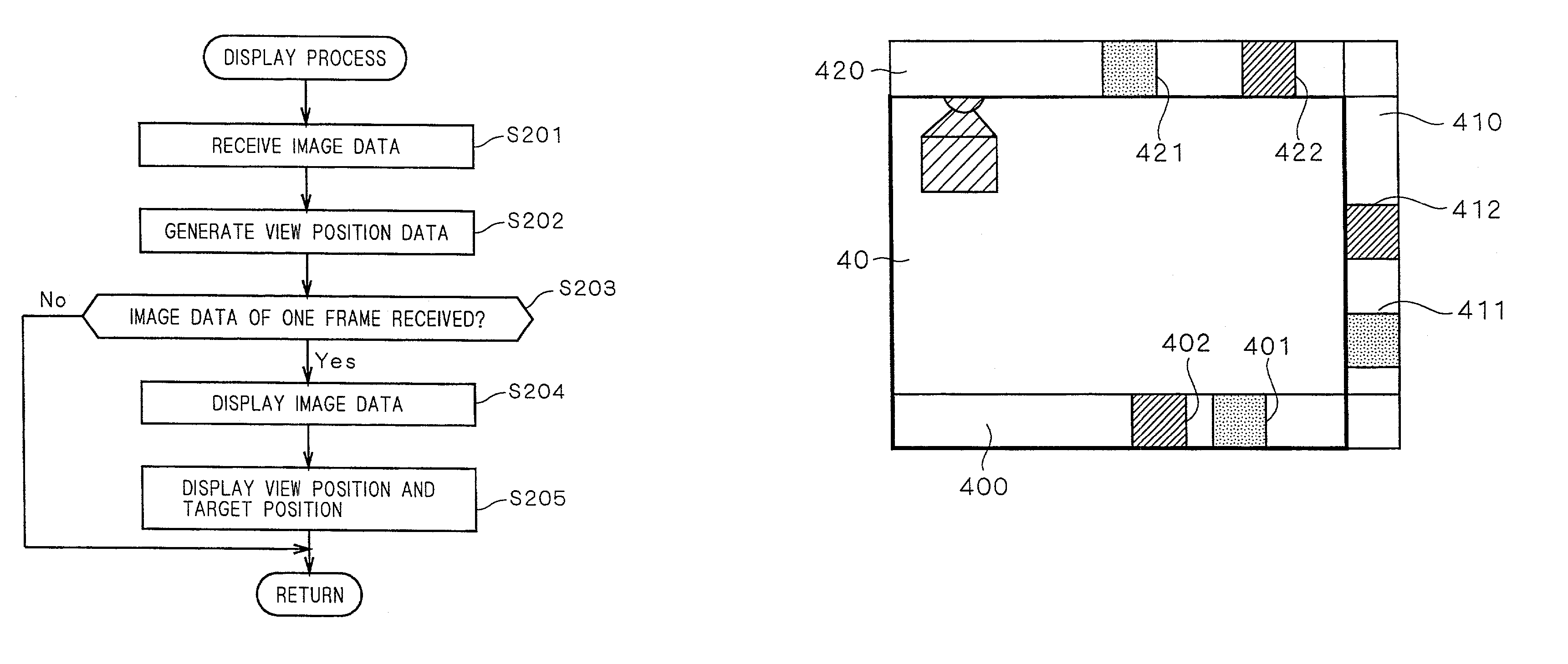
[0041]When a user (an operator) operates an image capturing apparatus by means of a portable phone, an image capturing system 1 according to the first embodiment counts the number of optical operation commands entered (inputted) from the portable phone by the user, determines a target position after changing a field of view in the image capturing apparatus and displays the target position, and also displays on the screen of the portable phone a view position of the image capturing apparatus at the time when the image data received by the portable phone is obtained.
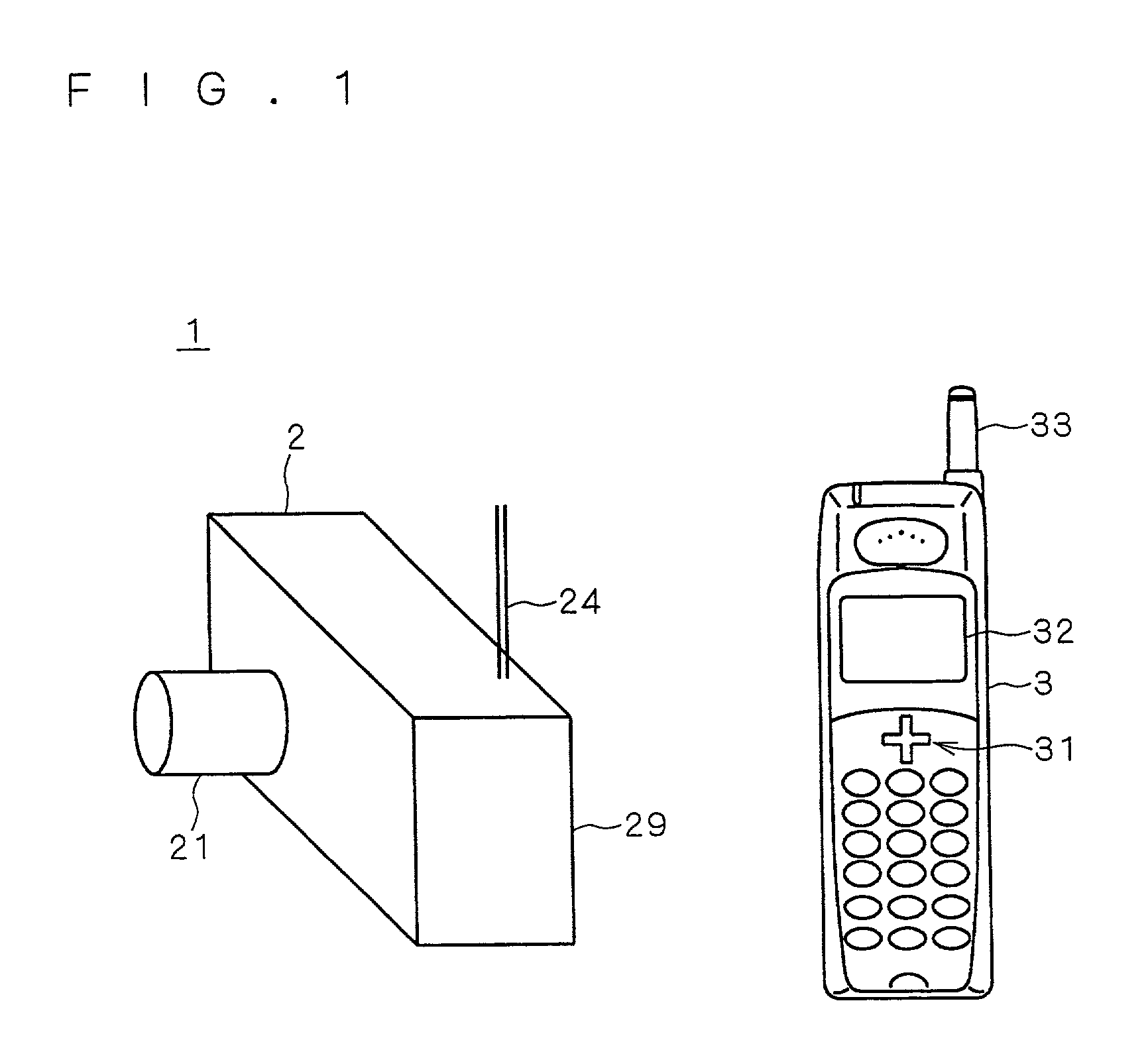
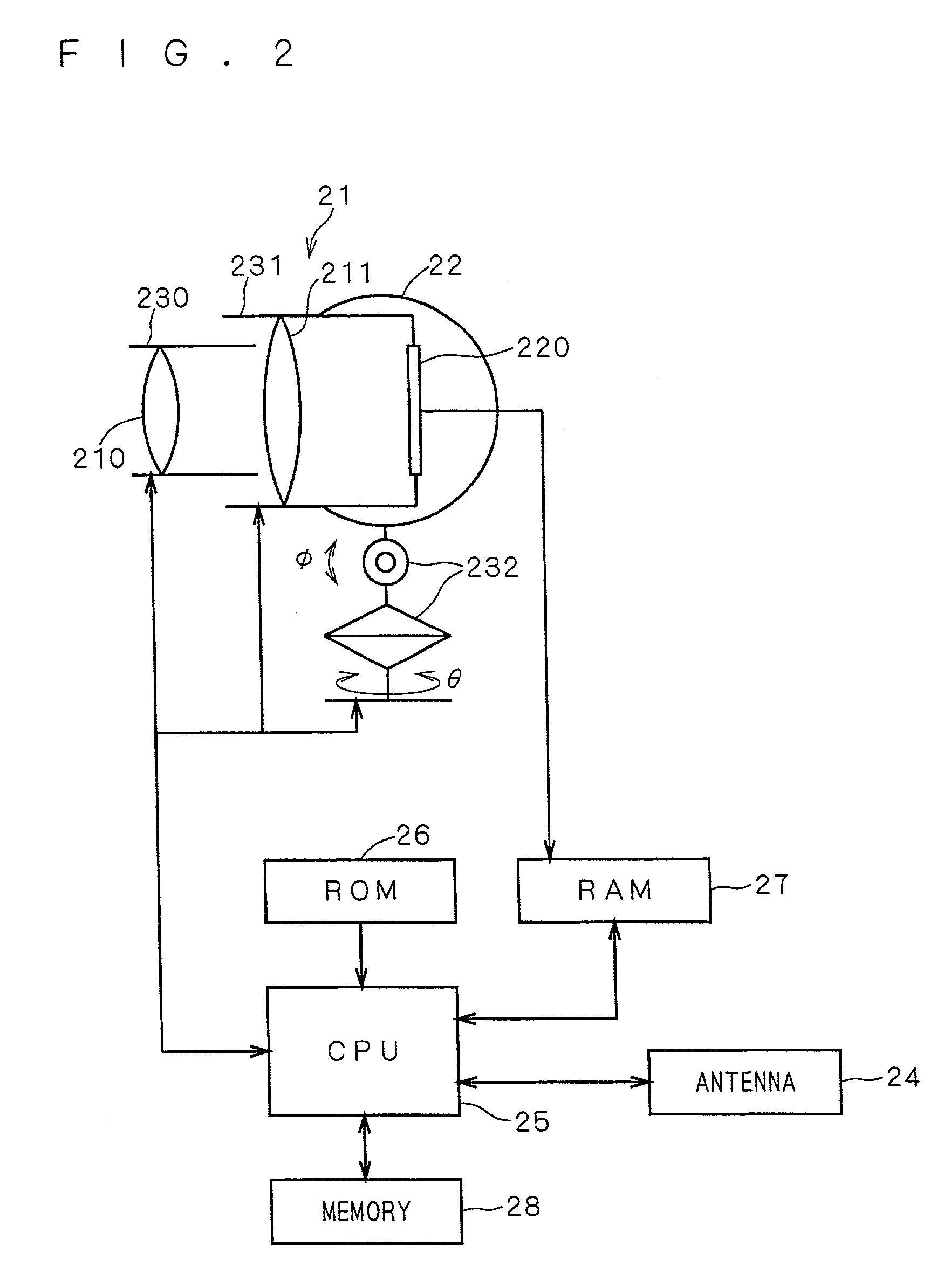
[0042]FIG. 1 is a view showing a configuration of the image capturing system 1 according to the first embodiment of the present invention. The image capturing system 1 comprises a camera (digital still camera or digital movie camera) 2 which embodies the image capturing apparatus and a portable phone 3 serving as a manual operating apparatus which can remotely operate the camera 2. Panning and tilting operations as will be...
second embodiment
[0082]In the first embodiment, the view position and the target position are displayed on the scroll bars provided in the image display section 32 of the portable phone 3, however, the view position and the target position may be displayed by using meters.
[0083]FIG. 11 and FIG. 12 are views showing examples of displaying a view position and a target position of the camera 2 on the image display section 32 of the portable phone 3 in the image capturing system 1 according to the second embodiment. The image capturing system 1 in the present embodiment has the similar configuration as the first embodiment, and hence the explanation thereof will be omitted.
[0084]FIG. 11 and FIG. 12 are views showing examples of screen displayed on the image display section 32 in a display process of the portable phone 3 according to the present embodiment. An image 50 shown in FIG. 11 is an image captured in the condition that an optical operation command is inputted from the operational section 31 and ...
third embodiment
[0088]In the above embodiment, the scroll bars and meters are provided on the image display section 32 for displaying the view position and the target position of the camera 2, however, it is also possible to set the display area of the image display section 32 of the portable phone 3 as a full range where the camera 2 can capture an image, and to display the latest image, view position and target position at corresponding points in the full range.
[0089]FIG. 13 is a flow chart showing the details of the display process (step S27 in FIG. 7) of the portable phone 3 according to the third embodiment. Operations of the display process of the portable phone 3 of the present embodiment will be explained by using FIGS. 13 to 15. The configuration of the image capturing system 1 according to the present embodiment is similar to that of the above embodiment.
[0090]First, likewise the first embodiment, the portable phone 3 receives image data 110 (step S301), and generates view position data 1...
PUM
 Abstract
Description
Claims
Application Information
 - R&D
- Intellectual Property
- Life Sciences
- Materials
- Tech Scout
- Unparalleled Data Quality
- Higher Quality Content
- 60% Fewer Hallucinations
Browse by: Latest US Patents, China's latest patents, Technical Efficacy Thesaurus, Application Domain, Technology Topic, Popular Technical Reports.
© 2025 PatSnap. All rights reserved.Legal|Privacy policy|Modern Slavery Act Transparency Statement|Sitemap|About US| Contact US: help@patsnap.com


