
Apparatus and method for outputting heart sounds

a technology of apparatus and sound, applied in the field of apparatus and method for outputting heart sounds, detecting heart sounds, can solve the problems of difficulty for physicians in accurately comparing the sounds heard using stethoscopes, ecg machines, and relatively high level of skill needed to perform this comparison

Inactive Publication Date: 2006-05-30
CARDIAC PACEMAKERS INC
View PDF56 Cites 53 Cited by
  • Summary
  • Abstract
  • Description
  • Claims
  • Application Information

AI Technical Summary

Benefits of technology

The invention is about a system that can be implanted in a person to detect and record heart sounds and cardiac electrical signals. The system includes a sensor, an interface circuit, and a control circuit. The control circuit receives the sensor signals, analyzes them, and sends the data to an external system. The external system then generates control signals based on the data and sends them to an output device, which produces the sounds and electrical signals that represent the heart. The system can detect multiple signals and send them to the external system simultaneously. The technical effect of this invention is the ability to accurately and non-invasively record heart sounds and cardiac electrical signals for analysis and treatment purposes.

Problems solved by technology

This method suffers from several disadvantages, including the need to use the stethoscope, the effect of various factors (e.g., the placement of the stethoscope, body fat, etc.) on the heart sounds, the need to electrically couple ECG probes to the patient's chest, the difficulties faced by the physician in accurately comparing the sounds heard using the stethoscope to the traces displayed by the ECG machine, and the relatively high level of skill needed to perform this comparison (especially if a physician is not available).
This method also does not continuously monitor for electrical-mechanical disassociation, thus making it difficult to detect disassociation occurring between visits to the physician, and does not provide the ability to produce a written record showing a detected disassociation.

Method used


Image

  • Apparatus and method for outputting heart sounds
  • Apparatus and method for outputting heart sounds
  • Apparatus and method for outputting heart sounds

Examples


Embodiment Construction

[0019]In the following detailed description, reference is made to the accompanying drawings, which form a part hereof, and in which is shown by way of illustration specific embodiments in which the present invention may be practiced. These embodiments are described in sufficient detail to enable those skilled in the art to practice the present invention, and it is to be understood that the embodiments may be combined, or that other embodiments may be utilized and that structural, logical and electrical changes may be made without departing from the spirit and the scope of the present invention. The following detailed description is, therefore, not to be taken in a limiting sense, and the scope of the present invention is defined by the appended claims and their equivalents.

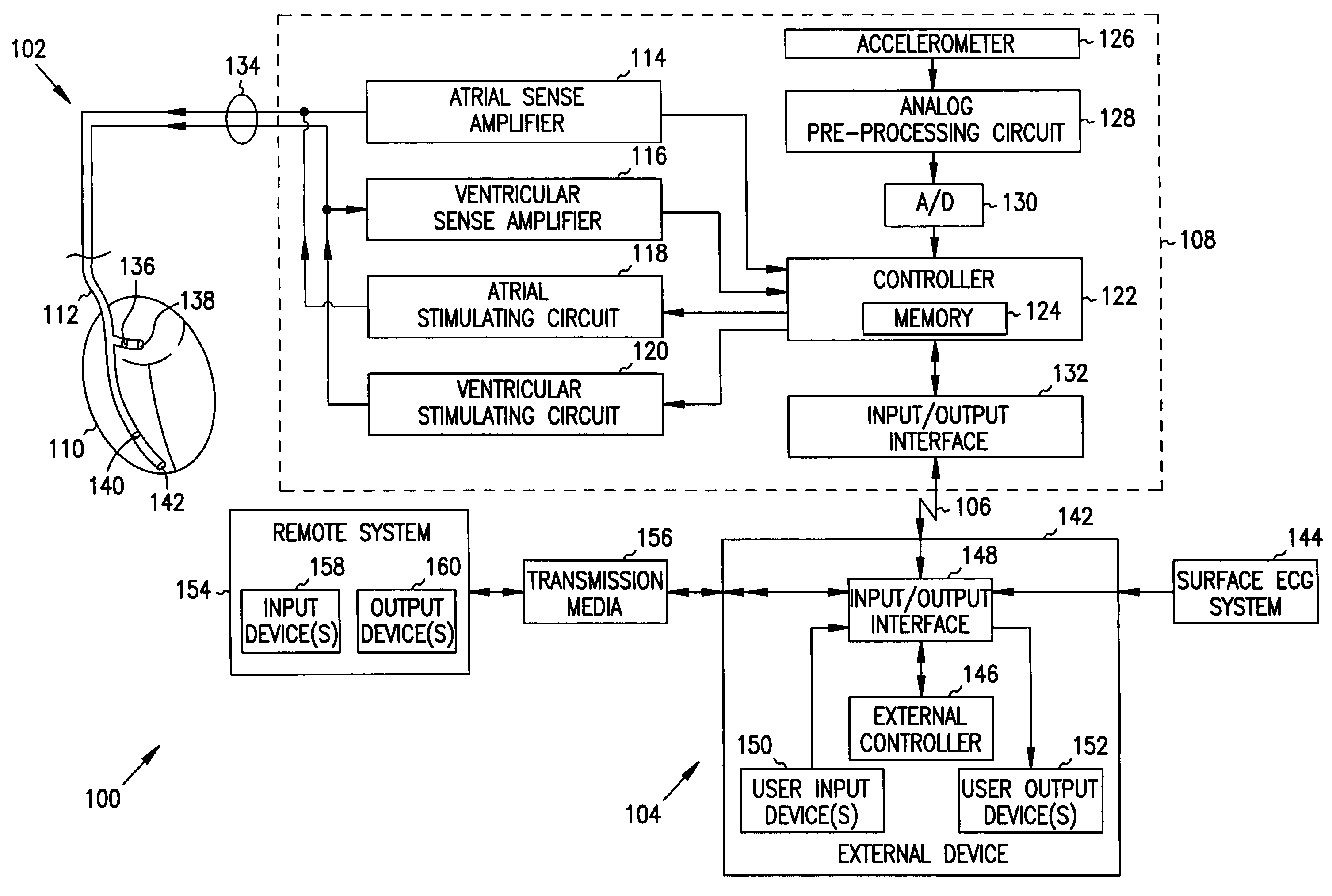
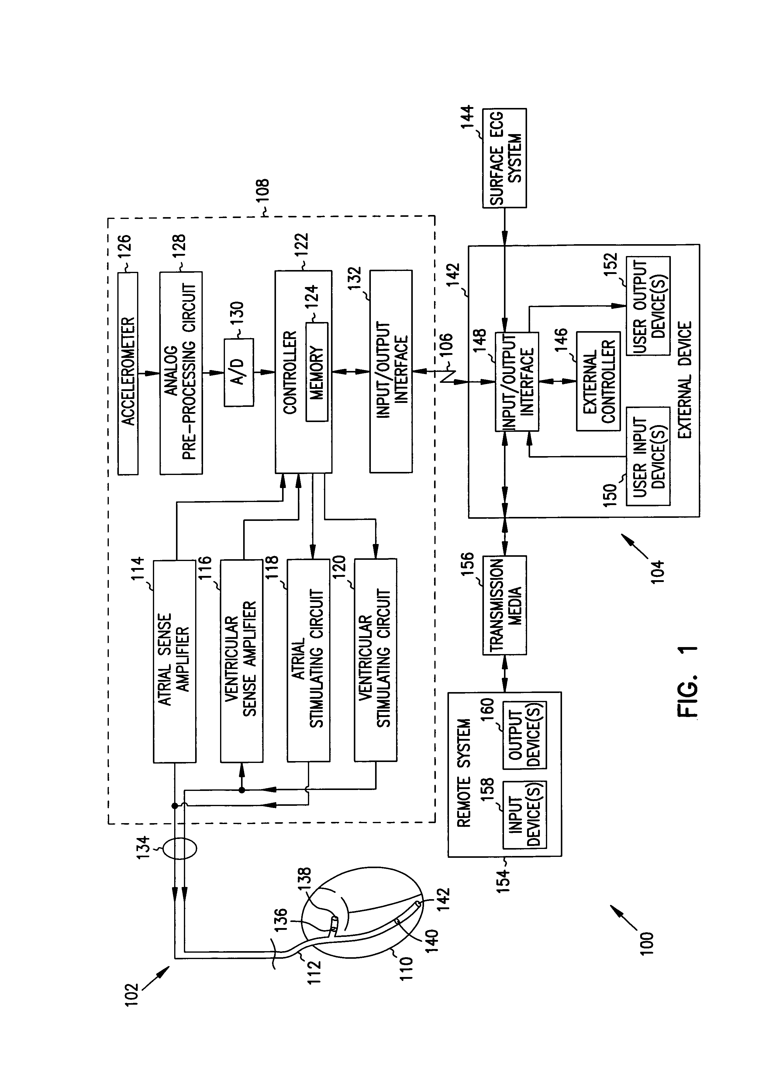
[0020]Referring to FIG. 1, an exemplary system 100 for outputting heart sounds in accordance with one embodiment of the present invention comprises an implantable system 102 and an external system 104. Implantable...


PUM


Abstract

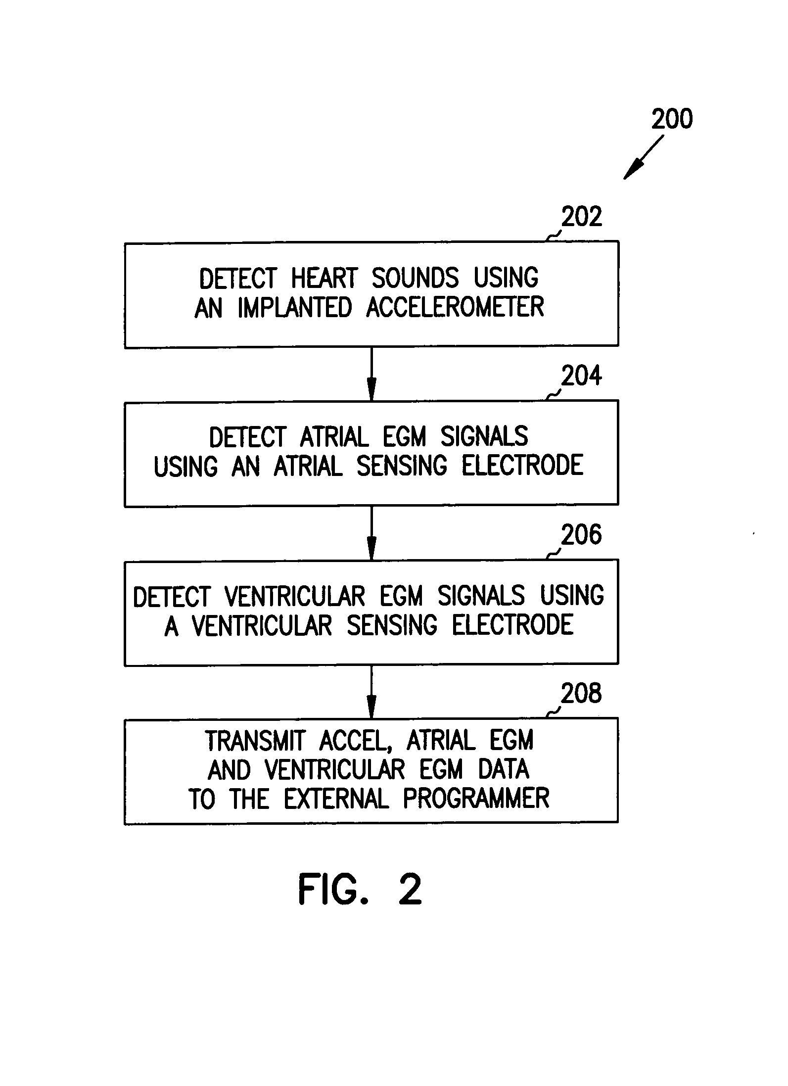
An apparatus for outputting heart sounds includes an implantable system and an external system. The implantable system includes a sensor for generating sensed signals representing detected heart sounds, an interface circuit and a control circuit for receiving the sensed signals, generating data representing the heart sounds therefrom, and transmitting the data to the external system via the interface circuit. The external system includes an interface circuit for communicating with the implantable system, and a control circuit for receiving the data representing the heart sounds and for generating control signals that cause an output device to generate outputs representing the sounds. The implantable system may also include a sensor(s) for detecting cardiac electrical signals. In this case, outputs representing the cardiac electrical signals are also output.

Description

FIELD OF THE INVENTION[0001]The present invention generally relates to the field of cardiac monitoring, and more particularly relates to detecting heart sounds using an implanted sensor, transmitting data indicative of the heart sounds to an external system, and outputting the heart sound data.BACKGROUND[0002]Cardiac pacemakers generally provide functions including sensing electrical signals generated by the heart, controlling stimulation of excitable tissues in the heart, sensing the response of the heart to such stimulation, and responding to inadequate or inappropriate stimulus or response (e.g., dysrhythmia) to deliver therapeutic stimuli to the heart. Some existing cardiac pacemakers also function to communicate with an external programmer device to support a variety of monitoring, diagnostic and configuration functions.[0003]Certain cardiac pacemakers include an internal accelerometer for measuring the level of activity of the patient (e.g., movement caused by walking around, ...

Claims


Application Information

Patent Timeline
Patent Type & Authority Patents(United States)
IPC IPC(8): A61B7/04A61B5/00A61B5/042A61B5/044A61B5/0452A61B7/02
CPCA61B5/042A61B7/023A61B5/742A61B7/04A61B5/04012A61B5/0002A61B5/0402A61B5/1118A61B5/04014A61B5/0031A61B5/044A61B5/0452A61B7/00A61B5/283A61B5/339A61B5/349A61B5/33A61B5/346
Inventor SCHEINER, AVRAMZHU, QINGSHENGOLIVE, ARTHUR L.VILLALTA, DON
Owner CARDIAC PACEMAKERS INC
Learn More