
Pedicure basin for pedicure station and salon chair

a pedicure station and basin technology, applied in the field of salon chairs, can solve the problems of uneven surface, not designed to bear all of the weight, damage to the pressurized spray nozzle,

Inactive Publication Date: 2006-05-30
THOMAS RICHARD
View PDF26 Cites 16 Cited by
  • Summary
  • Abstract
  • Description
  • Claims
  • Application Information

AI Technical Summary

Benefits of technology

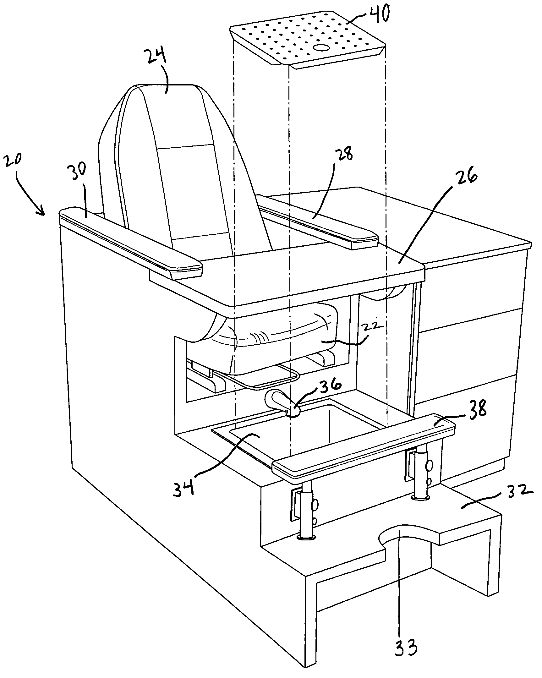
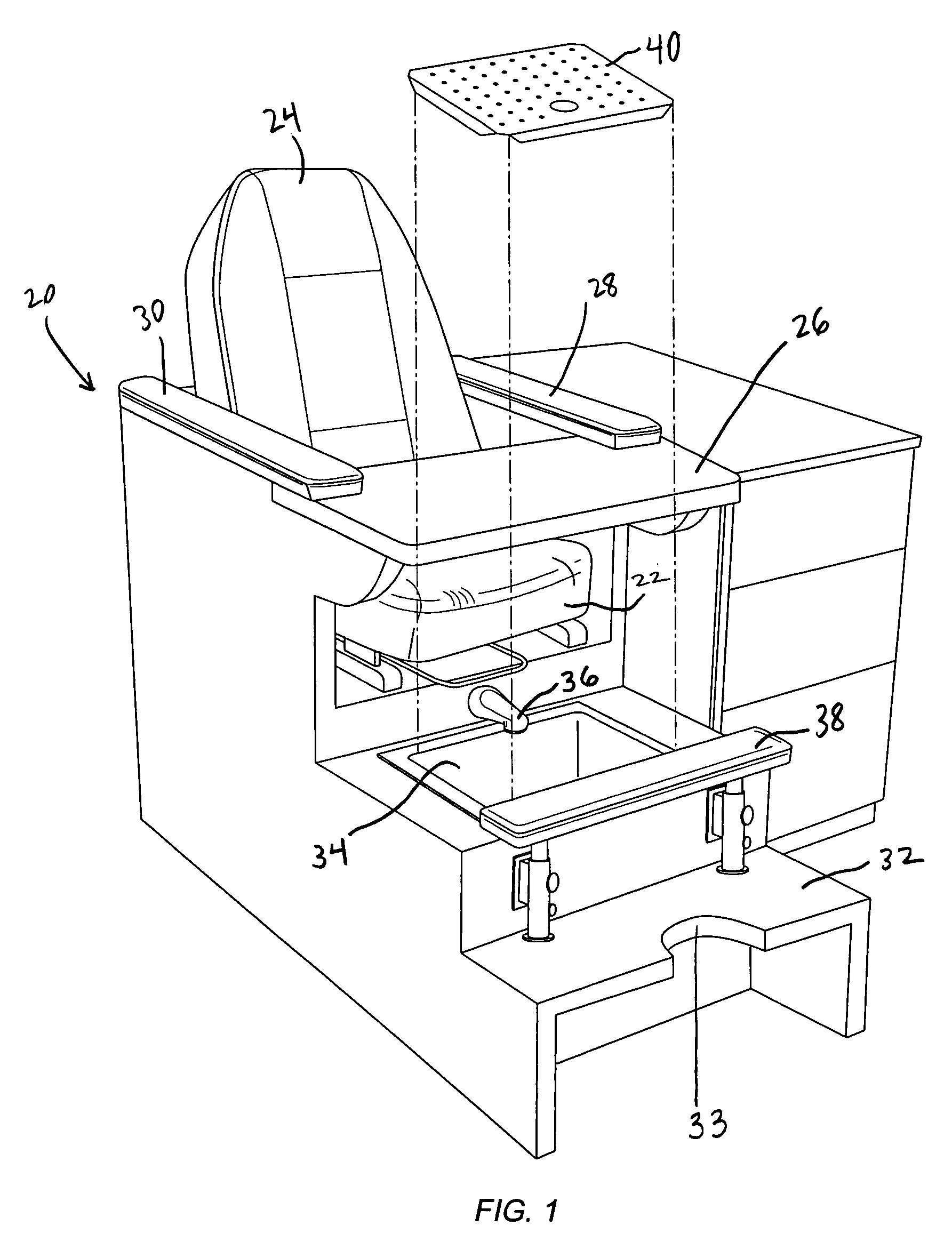
[0014]The salon chair of the present invention also preferably includes a front step disposed opposite the foot portion of the salon chair on the opposite side of the pedicure basin; this front step assists a user in stepping into and out of the pedicure basin as the user enters, and later exits, the salon chair. This forwardmost portion of the front step, i.e., the side extending away from the salon chair, preferably includes a groove projecting toward the pedicure basin. This groove in the front step is adapted to receive a leg of a salon technician's chair for allowing the salon technician to advance the technician's chair closer to the salon patron.

Problems solved by technology

Such pedicure basins, however, are usually not designed to bear all of the weight of a person, and clients who step into such basins often damage the pressurized spray nozzles provided at the bottom of such pedicure basins to provide the aforementioned whirlpool action.
Additionally, such spray nozzles provide a bumpy, irregular surface which is awkward to step upon.
Otherwise, the plexiglass platform would interfere with the whirlpool action of the pressurized water nozzles and prevent the pressurized jets of water from reaching the client's feet.
While such platform protected the floor of the pedicure basin from damage, the necessity to constantly insert and remove the plexiglass platform posed its own disadvantages for the service technician.

Method used


Image

  • Pedicure basin for pedicure station and salon chair
  • Pedicure basin for pedicure station and salon chair
  • Pedicure basin for pedicure station and salon chair

Examples


Embodiment Construction

[0026]FIG. 1 illustrates a salon chair 20 constructed in accordance with a preferred embodiment of the present invention. Salon chair 20 includes a seat 22, a backrest 24, and a pair of armrests 28 and 30. A manicure tabletop 26 is positioned at arm level and may be removably coupled to salon chair 20, as by sliding into retaining slots formed below armrests 28 and 30. Manicure tabletop 26 provides a resting surface for the hands of a patron seated in salon chair 20 for receiving a manicure. Tabletop 26 may be removed when the patron enters or exits salon chair 20.

[0027]Also shown in FIG. 1 is a pedicure basin 34 located at the foot of salon chair 20 below and forward of seat 22. Pedicure basin 34 includes a water inlet source, in the form of faucet 36, for adding water to pedicure basin 34. A padded footrest 38, adjustable in height, may also be provided to support the patron's feet during certain pedicure operations.

[0028]A front step 32 is provided in front of pedicure basin 34 o...


PUM


Abstract

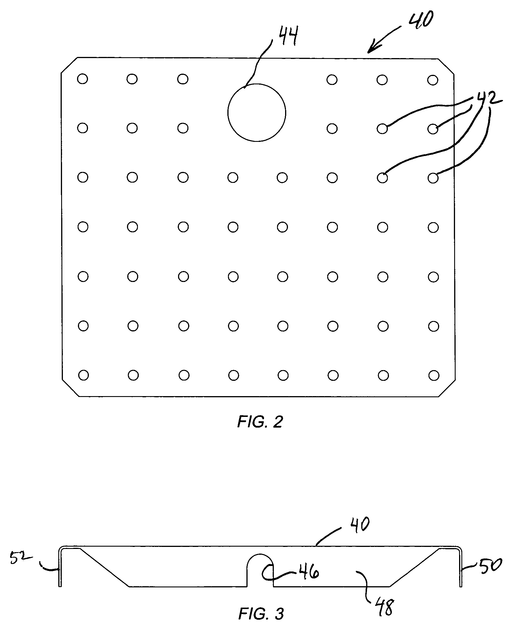
A salon chair includes a pedicure basin positioned between the foot of the chair and a front step opposite the foot of the chair. The pedicure basin includes a bottom floor, a perforated stepping surface above the bottom floor of the basin, and a nozzle assembly disposed between the bottom floor and the stepping surface for agitating water in the pedicure basin. Pressurized air is directed out of the nozzle assembly to induce a whirlpool action in the water held by the basin. The stepping surface may remain in the pedicure basin for days at a time, but may be removed when desired for cleaning purposes. The front step includes a cut-out, or groove, allowing allows a technician's chair to pull up closer to a person seated in the salon chair.

Description

FIELD OF THE INVENTION[0001]The present invention relates generally to salon chairs used for services such as pedicures, manicures, facials and other related services, and more specifically to such a chair having an improved pedicure basin.DESCRIPTION OF THE RELATED ART[0002]Chairs used in professional beauty salons have become particularly versatile, allowing a customer to receive a facial, manicure, and pedicure while sitting at a single work station. Such salon chairs may include a removable work tray installed after a client sits in the salon chair for resting the client's hand on such work tray to facilitate a manicure. Such salon chairs may also include a pedicure basin at the foot of the chair to facilitate pedicure services. The pedicure basin typically includes a faucet for adding water to the basin, a drain for draining water from the basin, and may further include water pressure jets for inducing a Jacuzzi-type whirlpool action to massage and clean the client's feet.[0003...

Claims


Application Information

Patent Timeline
IPC IPC(8): A47B83/02A47C16/02A47C7/50A47C7/62A47C7/68
CPCA47C1/04A47C1/11A47C16/02
Inventor THOMAS, RICHARD
Owner THOMAS RICHARD
Learn More