
Lens for eye and method for marking thereof

a technology for eye lenses and lenses, applied in the field of eye lenses, can solve the problems of high defect or rejection ratio of ophthalmic lenses, inability to develop color, and inability to meet the needs of eye care, so as to achieve the effect of still more effective color developmen

Inactive Publication Date: 2006-05-16
MENICON CO LTD
View PDF11 Cites 10 Cited by
  • Summary
  • Abstract
  • Description
  • Claims
  • Application Information

AI Technical Summary

Benefits of technology

The method enables the formation of clear, readable marks throughout the lens depth, resistant to cleaning-induced discoloration and maintains mechanical strength, improving manufacturing efficiency and lens durability.

Problems solved by technology

However, for the mark formed by the former printing method, there are concerns that the dyes or colorants of the mark may be flowed off, discolor, or peel off due to various treatments repeatedly conducted on the lens, such as cleaning of the lens by rubbing and repetitive disinfection.
Moreover, marking of an ophthalmic lens by the printing method requires many process steps for marking the ophthalmic lens, such as a drying step after the printing, and also requires many devices for the process steps.
In addition, the ophthalmic lens needs to be handled frequently, undesirably resulting in a high defect or reject ratio of the ophthalmic lens.
Accordingly, the cost of manufacture of the ophthalmic lens is undesirably increased, causing a problem of poor economy.
Meanwhile, the mark formed by the latter laser radiation marking method is not easily readable.
Further, deposits are likely to accumulate in the grooves or recesses made by the laser radiation, causing undesirable troubles such as irritation of the eye of the lens user.
However, there are also concerns for the contact lens prepared by the above-mentioned method that the dye may be flowed off, or the pattern may be discolored or peeled off, due to cleaning of the lens by rubbing and / or repetitive disinfection.

Method used


Image

  • Lens for eye and method for marking thereof
  • Lens for eye and method for marking thereof
  • Lens for eye and method for marking thereof

Examples


examples

[0066]To further clarify the concept of the present invention, some examples of the invention will be described. It is to be understood that the invention is not limited to the details of the illustrated examples and the foregoing description, but may be embodied with various changes, modifications and improvements, which may occur to those skilled in the art without departing from the scope of the invention defined in the attached claims.

[0067]Production of an Ophthalmic Lens Material

[0068]Rhodamine B in the above TABLE 1 was obtained as the rhodamine derivative, while a methyl methacrylate and an ethyl methacrylate were obtained as the alkyl (meth)acrylate. There was also prepared an ethyleneglycol dimethacrylate, while tris(trim ethylsiloxy)silylpropyl methacrylate, tris(trimethylsiloxy)silylstyrene, and trifluoroethyl methacrylate were also prepared as the other polymerizable components (above-mentioned optional components). In addition, 2,2-azobis(2,4-dimethylvaleronitrile) was...


PUM

PropertyMeasurementUnit
wavelengthaaaaaaaaaa
temperatureaaaaaaaaaa

Abstract

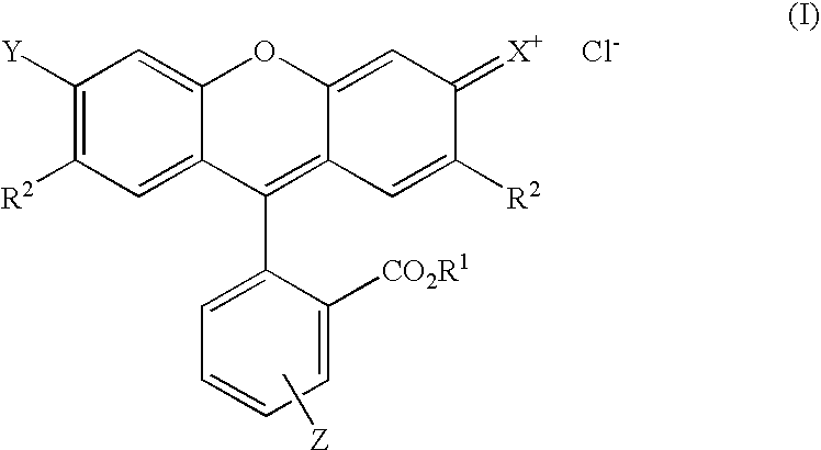
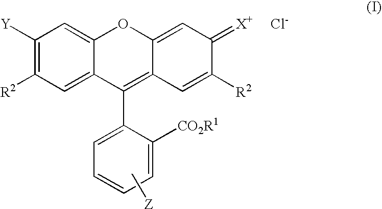
It is an object of the present invention to provide an ophthalmic lens characterized in that it is capable of developing a color at a position where a light is irradiated, and to provide a marking method of the ophthalmic lens. It is another object of the present invention to provide an ophthalmic lens, which can form a clear and easily readable mark, without causing problems such as discoloration of the mark, caused by cleaning of the lens by rubbing, or deterioration of the mechanical strength of the lens, and to provide a marking method of the ophthalmic lens. The ophthalmic lens of the present invention is obtained by a polymerization of a polymerizable composition of monomers, which contains an alkyl (meth)acrylate as an essential polymerizable component, and this polymerization is carried out while the rhodamine derivative is present in the composition.

Description

CROSS REFERENCE TO RELATED APPLICATION[0001]This application is a continuation application of International Application Ser. No. PCT / JP2003 / 013459, having an international filing date of Oct. 22, 2003, and claims the benefit of Japanese Application 2002-340504, filed Nov. 25, 2002.TECHNICAL FIELD[0002]The present invention relates in general to an ophthalmic lens and a marking method thereof. More particularly, the present invention relates to an ophthalmic lens, which is arranged to contain, in its material, a rhodamine derivative whose color can be changed by an irradiation of a light, and to a marking method of the ophthalmic lens.BACKGROUND ART[0003]Conventionally, an ophthalmic lens such as a contact lens or an intraocular lens is provided with an identifying mark in the form of characters such as numbers and alphabets, figures, symbols, etc., principally for easy distinction between the front and back surfaces of the lens or between lenses for the left and right eyes, and / or i...

Claims


Application Information

Patent Timeline
Patent Type & Authority Patents(United States)
IPC IPC(8): G02C7/04C08F2/44G02B1/04G02C7/02
CPCG02B1/041G02C7/021C08L33/06
Inventor NAKADA, KAZUHIKOMATSUMOTO, MASAHIRO
Owner MENICON CO LTD
Learn More