
Glue tote

a technology of glue and tote, which is applied in the field of glue tote, can solve the problems of brittle piping, failure, and inability to withstand the weight of glue, and achieve the effects of preventing the brittleness of the piping

Inactive Publication Date: 2006-05-16
MUMFORD HARRY JAMES
View PDF15 Cites 6 Cited by
  • Summary
  • Abstract
  • Description
  • Claims
  • Application Information

AI Technical Summary

Benefits of technology

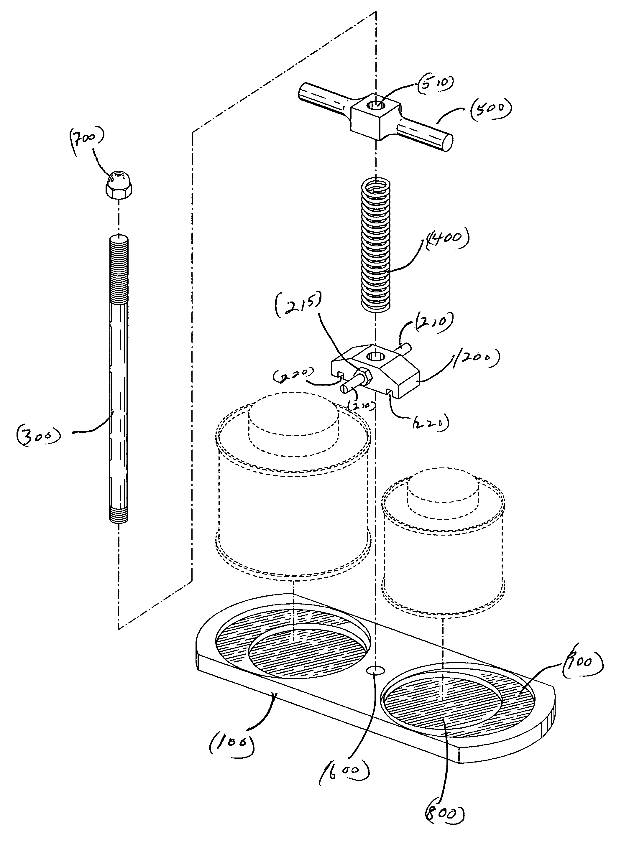
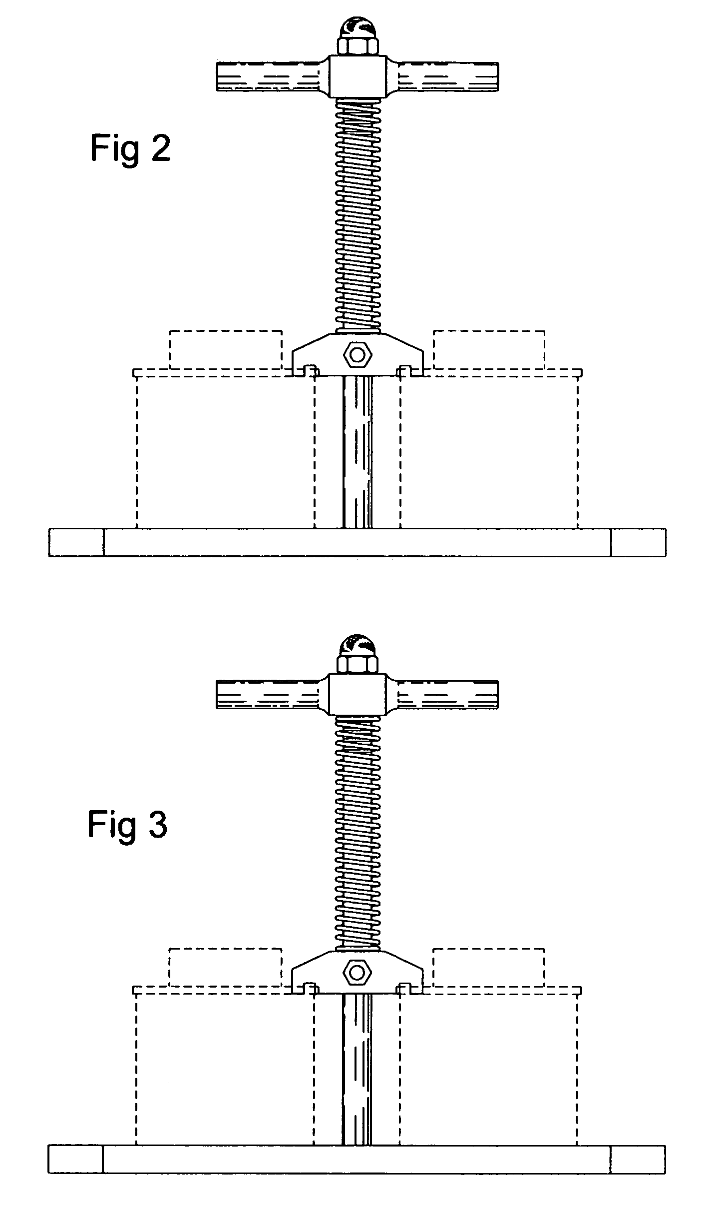
[0011]A spring is located between the underside of the handle and the top surface of the clamp of the device. On the point of contact with the top of the cans the clamp has a recessed or grooved lip, which allows the clamp to fit over the lip of the container. The downward pressure of the spring insures a secure fit. On the sides of the clamp are two pieces of stock, which extend perpendicular from the sides of the clamp and allow the user a convenient device to pull the clamps off the cans.
[0012]On the top surface of the base of the device are recessed rings, which are the diameter of a pint and a quart sized can. This will ensure that the cans will not slip during normal operation as it is being clamped and helps to insure that the cans remain in place during normal use.
[0013]A “T” handle at the top of the spindle, which is secured by a hex nut, provides an easy means to carry the device.

Problems solved by technology

Without the use of the glue and the cleaner the piping becomes brittle and fails.
The environment is dirty and often has uneven surfaces.
One of the risks in the field for the plumber is that the plumber may accidentally knock the can of cleaner or glue over.
This results in waste of the product and waste of time for the plumber.
Both the presence of foreign material and air will destroy the cleaner and glue.

Method used


Image

  • Glue tote
  • Glue tote
  • Glue tote

Examples


Embodiment Construction

[0023]According to FIG. 1 this device consists of a bottom or base section 100, a clamp 200, a spindle 300, which is threaded on both ends, a spring 400 and a T handle 500. The bottom section 100 is approximately 11¾″ inches long by one-half inch thick. The bottom section has a width of approximately 4⅜″ inches. FIG. 8 is an exploded view of the device and shows the recessed grooves 220 on the underside of the clamp 200.

[0024]In the center of the base section there is a tapped and threaded hole 600, which is approximately one-half inch in diameter (FIG. 1).

[0025]One end of the threaded spindle 300, is screwed into the hole 600 on the bottom section. The spindle 300 extends through a hole in the center of the clamp 200 and through a hole in the center 510 of the T handle 300. It is secured in place by a hex nut 700.

[0026]On the top of the bottom or base section 600 two recessed concentric circles, 800 and 900, are formed on the top surface of the base section. These concentric circle...


PUM


Abstract

The embodiment of this invention is disclosed, which describes a device to carry two cans at one time in a secure fashion. This invention allows the user of the device to carry either pint or quart sized cans to any site in a secure fashion. It rests on a base, which will allow the user to lay it on a level surface. The cans themselves are securely fastened to the device using a spring, which is located between the bottom of a handle and the top surface of a clamp. A T-handle allows the user to carry the device from site to site.

Description

CROSS REFERENCES TO RELATED APPLICATIONSNoneSTATEMENT REGARDING FEDERALLY SPONSORED RESEARCHNo federal research money was used in the development of this invention.REFERENCE TO APPENDIXNo appendix accompanies this applicationBACKGROUND OF THE INVENTION[0001]Certain tradesman, particularly construction workers, are required to bring various materials to job sites. Sometimes the necessary equipment is in bags, bottles, rolls or cans. This device allows the worker to carry two same sized cans in a handy carrying device. This application will describe how a plumber for instance will use the device.[0002]Most plumbers are very familiar with PVC (Polyvinyl Chloride) piping or coated PVC. It is lightweight, very durable and is very commonly used in houses and outdoor applications such as irrigation systems. However, in order to connect the PVC together the plumber must apply both a cleaner and a glue to the pipe in order to make a secure and tight fit of the pieces of PVC piping.[0003]With...

Claims


Application Information

Patent Timeline
IPC IPC(8): A44B7/00
CPCB25H3/00Y10T24/44641
Inventor MUMFORD, HARRY JAMES
Owner MUMFORD HARRY JAMES
Learn More