
Solid catadioptric lens with a single viewpoint

a catadioptric lens and single viewpoint technology, applied in the field of lenses, can solve the problems of cumbersome, expensive and large, and the limited range of catadioptric zoom relay telescopes and lens assemblies, and achieve the effects of compactness, ruggedness and effective

Active Publication Date: 2006-05-02
ELECTRONICS SCRIPTING PRODS
View PDF38 Cites 139 Cited by
  • Summary
  • Abstract
  • Description
  • Claims
  • Application Information

AI Technical Summary

Benefits of technology

"The invention is a solid catadioptric lens with a single viewpoint that can be used in a vision system. The lens has an optical axis and a spherical refractive surface with a center of view. It has an ellipsoidal reflective surface facing the spherical refractive surface with a first focus coincident with the center of the spherical refractive surface. The lens can have a refractive shaping surface or a reflective surface with an aperture for enforcing the single viewpoint. The lens can be made of glass or plastic and can be used for imaging or scanning applications. An optical relay can be used to pass the light from the lens to the application. The technical effects of the invention include a single viewpoint, improved image quality, and reduced aberrations."

Problems solved by technology

Although these catadioptric systems can have a large field of view and can satisfy the single viewpoint requirement they are cumbersome, expensive and large.
It is difficult to satisfy all of the above conditions with a single system.
The catadioptric zoom relay telescopes and lens assemblies are usually limited to a small field of view and many do not have a single viewpoint.
Unfortunately, none of the prior art teachings provide a compact, effective and easy to manufacture single viewpoint lens that can be used in vision systems requiring a panoramic projection or perspective view of objects distributed over a large field of view.

Method used


Image

  • Solid catadioptric lens with a single viewpoint
  • Solid catadioptric lens with a single viewpoint
  • Solid catadioptric lens with a single viewpoint

Examples


Embodiment Construction

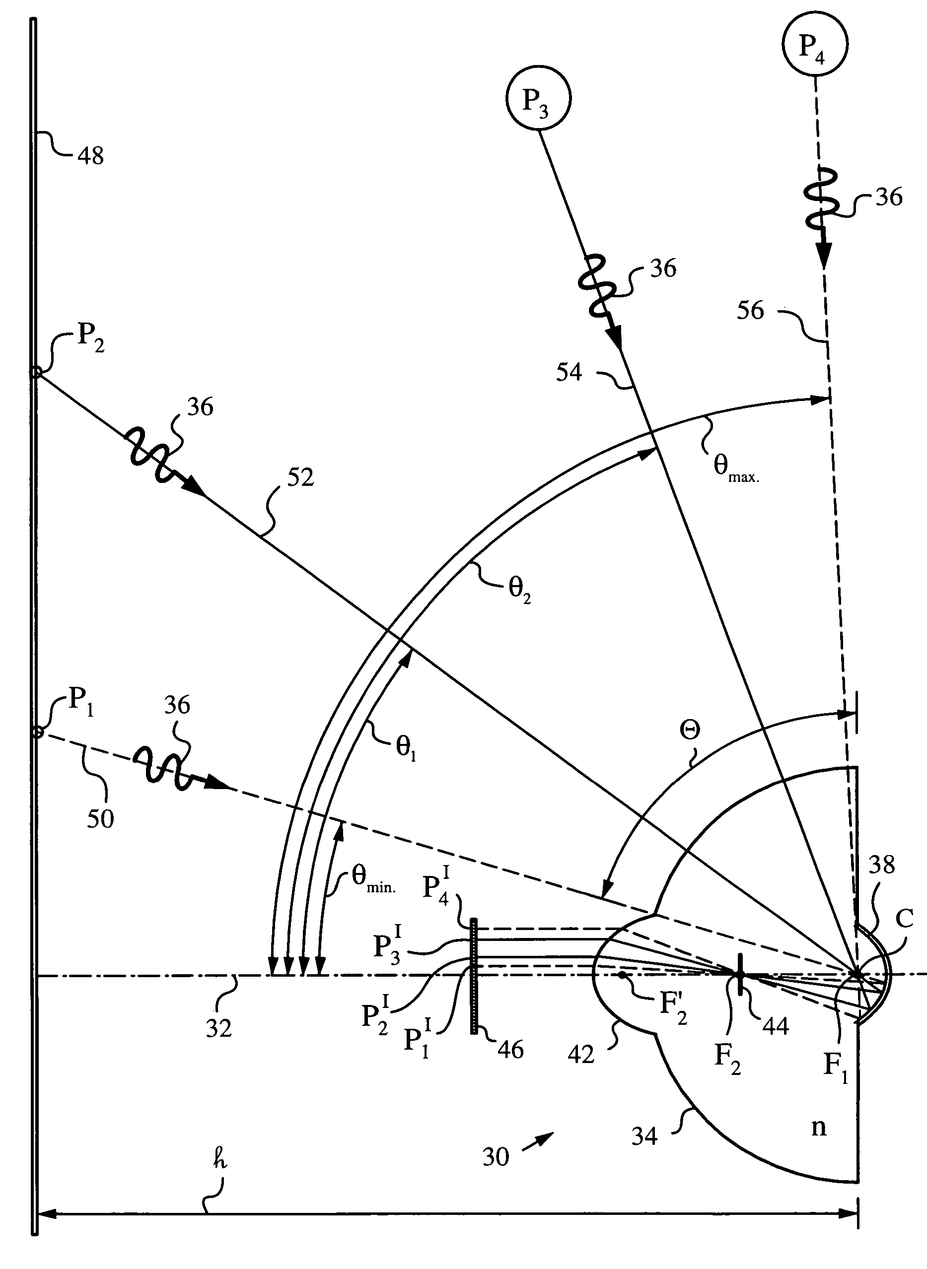
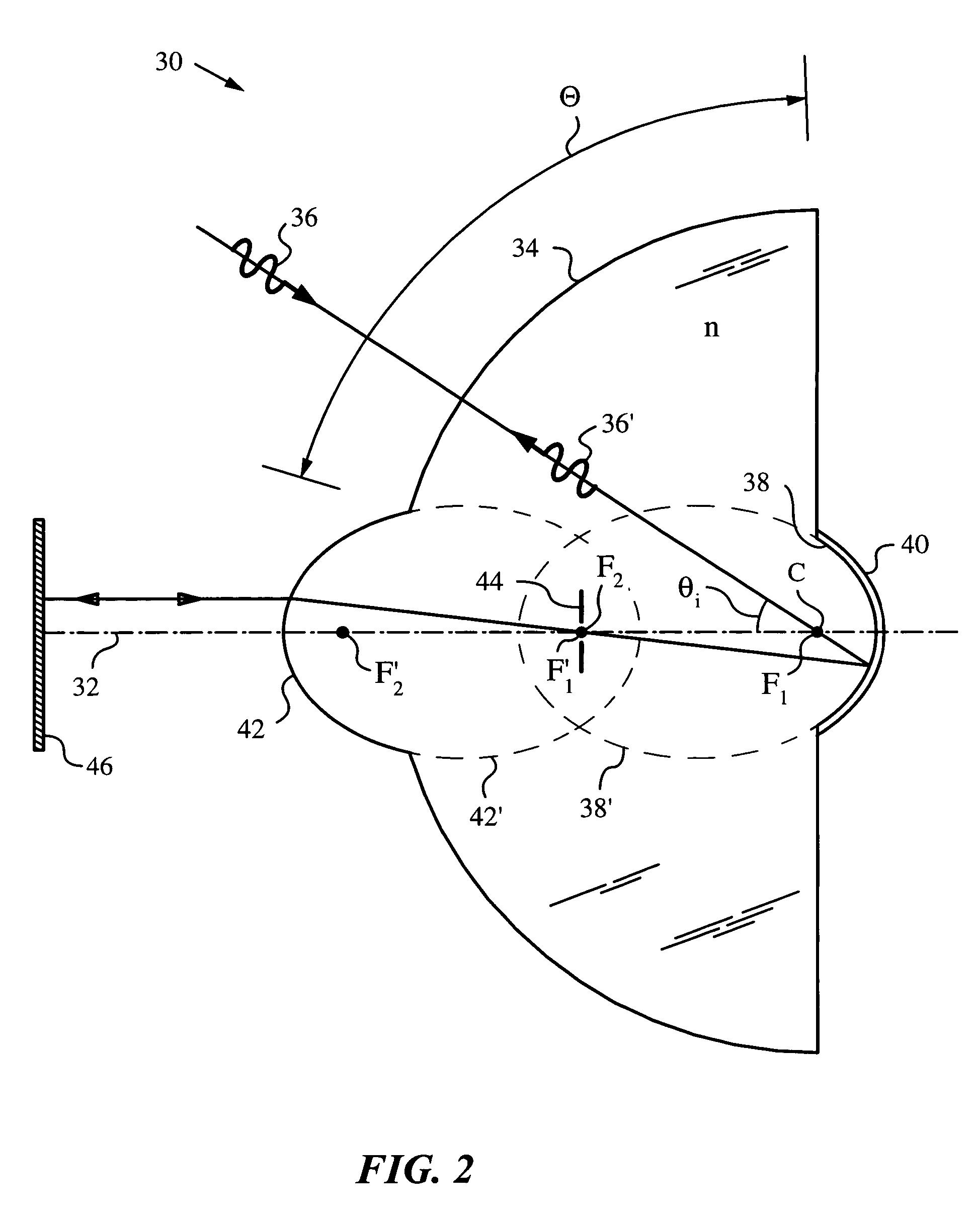
[0032]The present invention will be best understood by first referring to an embodiment of a single viewpoint solid catadioptric lens 30 as shown in FIG. 2 in cross-sectional side view. Lens 30 has an optical axis 32 and is made of an optical material of index n. Preferably, the optical material is uniform and exhibits substantially no or very little variation of index n. Suitable materials include glasses and plastics, such as moldable plastics and other optical materials.

[0033]Lens 30 has a spherical refractive surface 34 with a center C on optical axis 32. A light 36 propagating to and a light 36′ propagating from center C traverses spherical refractive surface 34 at normal incidence. Spherical refractive surface 34 defines a solid angle Θ over which lens 30 gathers light 36 and into which lens 30 projects light 36′.

[0034]Lens 30 has an ellipsoidal reflective surface 38 facing spherical refractive surface 34. Ellipsoidal reflective surface 38 can be made reflective by providing i...


PUM


Abstract

A solid catadioptric lens with a single viewpoint has a spherical refractive surface with a center C on an optical axis of the lens. An ellipsoidal reflective surface of the lens faces the spherical refractive surface such that a first focus F1 of the ellipsoidal reflective surface is coincident with the center C of the spherical refractive surface. Furthermore, the lens has a shaping surface facing the ellipsoidal reflective surface for shaping a light that passes the single viewpoint. The shaping surface can be refractive, reflective or semi-transparent and its shape can be ellipsoidal with its first focus F1′ coincident with the second focus F2 of the ellipsoidal reflective surface. The single viewpoint of the lens is at the center C of the spherical reflective surface and is enforced with an aperture that can be positioned at various points inside, on a surface or even outside the lens, depending on the type of shaping surface chosen.

Description

FIELD OF THE INVENTION[0001]The present invention relates generally to lenses for applications such as vision and imaging where a single viewpoint is required, and in particular to catadioptric lenses having a single viewpoint.BACKGROUND OF THE INVENTION[0002]Applications in computational vision such as ego-motion estimation and tracking often require imaging a large field of view. It is also desirable for an imaging system to have a single viewpoint in order to produce geometrically correct perspective images from the panoramic images obtained from the imaging system. The single and fixed viewpoint constraint requires that an imaging system only capture light that is passing through a single point in three dimensional space, thus sampling the 5-dimensional plenoptic function at that point, which is known as the effective viewpoint. Such imaging systems have been realized by assemblies of curved mirrors and lenses. Although these catadioptric systems can have a large field of view a...

Claims


Application Information

Patent Timeline
Patent Type & Authority Patents(United States)
IPC IPC(8): G02B23/00G02B13/06G02B17/08
CPCG02B13/06G02B17/086G02B13/22G02B13/18
Inventor MANDELLA, MICHAEL J.
Owner ELECTRONICS SCRIPTING PRODS
Learn More