
Automatic switch

a switch and automatic technology, applied in the direction of electrical apparatus casings/cabinets/drawers, coupling device connections, hermetically sealed casings, etc., can solve the problems of short circuit, circuit board damage due to vibration, etc., and achieve low melting point, good strength, and high rigidity.

Inactive Publication Date: 2006-04-25
ATEN INT CO
View PDF20 Cites 30 Cited by
  • Summary
  • Abstract
  • Description
  • Claims
  • Application Information

AI Technical Summary

Benefits of technology

[0004]A primary object of the present invention is to provide a plug-type automatic switch for a user to access and control multiple computer configurations through one single switch. The automatic switch includes a main body externally provided with connector ports and enclosing an internal circuit board. The main body has an integrally injection-molded plastic enclosure to provide good weather-resistance, impact-resistance, and absolute protection of the internal circuit board and circuits thereon.
[0007]The circuit-protecting layer of the main body is made of a plastic material having a low melting point to avoid damages to circuits provided on the circuit board during the injection molding.
[0008]The outer case of the main body has good strength and high rigidity and therefore provides excellent protection to the internal circuit board and the entire main body of the automatic switch.
[0009]The anti-slopping layer of the main body has soft surface to enable firm holding of the main body and convenient plugging and unplugging of signal cables in and from the main body.

Problems solved by technology

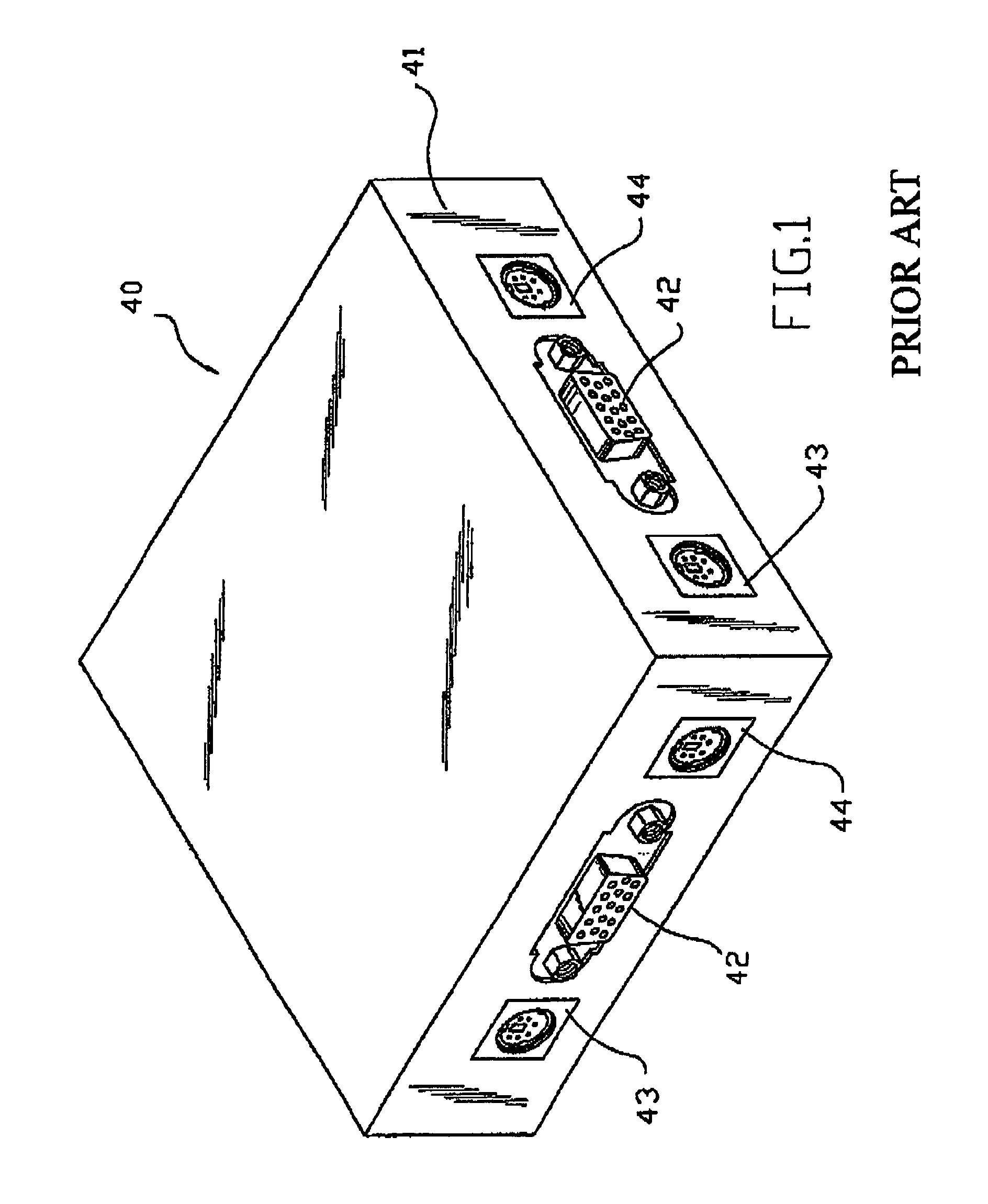
The automatic switch 40 is normally positioned on a host enclosure of a computer configuration and tends to unexpectedly fall off the host enclosure to result in a damaged circuit board due to vibration.
Moreover, when a high humidity exists, moisture in the air tends to attach to the circuit board to cause short circuit.

Method used


Image

  • Automatic switch
  • Automatic switch
  • Automatic switch

Examples


Embodiment Construction

[0015]Please refer to FIG. 2 that is a front view of an automatic switch 10 according to an embodiment of the present invention. As shown, the automatic switch 10 includes a main body 20 having connector ports provided on external walls thereof, and more than one or two sets of cable-connected connectors 30 directly extended from the main body 20.

[0016]Please refer to FIGS. 3 and 4 that are perspective and cross-sectional views, respectively, of the main body 20 of the automatic switch 10 of the present invention. The main body 20 has an integral enclosure that is formed through three times of injection molding to include a circuit-protecting layer 21 for enclosing a circuit board 24 provided in the main body 20, an outer case 22 enclosing the circuit-protecting layer 21, and an anti-slipping layer 23 coating an outer surface of the outer case 22.

[0017]It is to be noted that the circuit-protecting layer 21 of the main body 20 is in completely close contact with the circuit board 24,...


PUM


Abstract

An automatic switch includes a main body having connector ports provided thereon, more than one or two sets of cable-connected connectors directly extended from the main body, and a circuit board provided in the main body and electrically connected to the sets of cable-connected connectors via signal cables. The main body has an integral enclosure formed through multiple times of injection molding to include a circuit-protecting layer for enclosing the circuit board, an outer case enclosing the circuit-protecting layer, and an anti-slipping layer coating an outer surface of the outer case.

Description

BACKGROUND OF THE INVENTION[0001]The present invention relates to an automatic switch for a user to automatically switch between two or more computer configurations, and more particularly to an automatic switch that has an integrally injection-molded enclosure to provide good weather-resistance, impact-resistance, and absolute protection of an internal circuit board thereof.[0002]The highly developed electronic and information technologies enable people to collect required information or to trade directly over networks via computers, making computers a requisite tool in people's work, learning, entertainments, leisure activities, and daily life.[0003]For people to access two or more computers at the same time, there is developed an automatic switch to enable a user to automatically switch among different signal paths. FIG. 1 shows a conventional automatic switch 40 that is configured into a box 41. The box 41 is internally provided with a circuit board (not shown). Ports 42, 43, and...

Claims


Application Information

Patent Timeline
Patent Type & Authority Patents(United States)
IPC IPC(8): H05K5/00H05K5/04H05K5/06G06F3/023H01H9/04H01R27/02H01R31/00
CPCG06F3/023H01H9/04H01R27/02H01R31/005H05K5/065
Inventor CHEN, KEVIN
Owner ATEN INT CO
Learn More