
Data storage device, control device, off-track control method, and control method

Inactive Publication Date: 2006-04-25
HITACHI GLOBAL STORAGE TECH NETHERLANDS BV
View PDF6 Cites 28 Cited by
  • Summary
  • Abstract
  • Description
  • Claims
  • Application Information

AI Technical Summary

Benefits of technology

[0013]In this connection, it is an object of the present invention to effectively prevent an occurrence of an operational error in a correction operation based on an output from the sensor by dynamically controlling the gain of the sensor.
[0024]Here, more specifically, the step of generating a correction signal is performed in such a manner that the correction signal for a rotational vibration is generated based on output signals of a plurality of linear acceleration sensors. Then, the step of estimating an effect of supplying the correction signal includes the steps of: calculating appropriate gains in the individual linear acceleration sensors based on the output signals of the plurality of linear acceleration sensors; and estimating the effect of supplying the correction signal to the servo loop based on the obtained appropriate gains of the linear acceleration sensors.

Problems solved by technology

For example, off-track becomes a problem when data recorded on a data-track other than a target data track is overwritten during data write.
Such variations in gain of the linear acceleration sensors occur in the manufacturing process of the linear acceleration sensors, and it is difficult to remove the variations completely.
Also in such cases, a vibration component in the linear direction will be undesirably included in the vibration detected by the sensors.
Furthermore, even if the vibration in the rotational direction of the disk drive is detected by use of the rotational acceleration sensor, the rotational acceleration sensor undesirably will have some sensitivity for the vibration in the linear direction when the center of gravity of the rotational electrode and the center of rotation thereof do not coincide with each other accurately due to an error in the manufacturing process of the rotational acceleration sensor or the like.
Therefore, such a correction will rather cause the off-track.

Method used


Image

  • Data storage device, control device, off-track control method, and control method
  • Data storage device, control device, off-track control method, and control method
  • Data storage device, control device, off-track control method, and control method

Examples


Embodiment Construction

[0040]The embodiment of the present invention will be described below in detail by exemplifying a hard disk device.

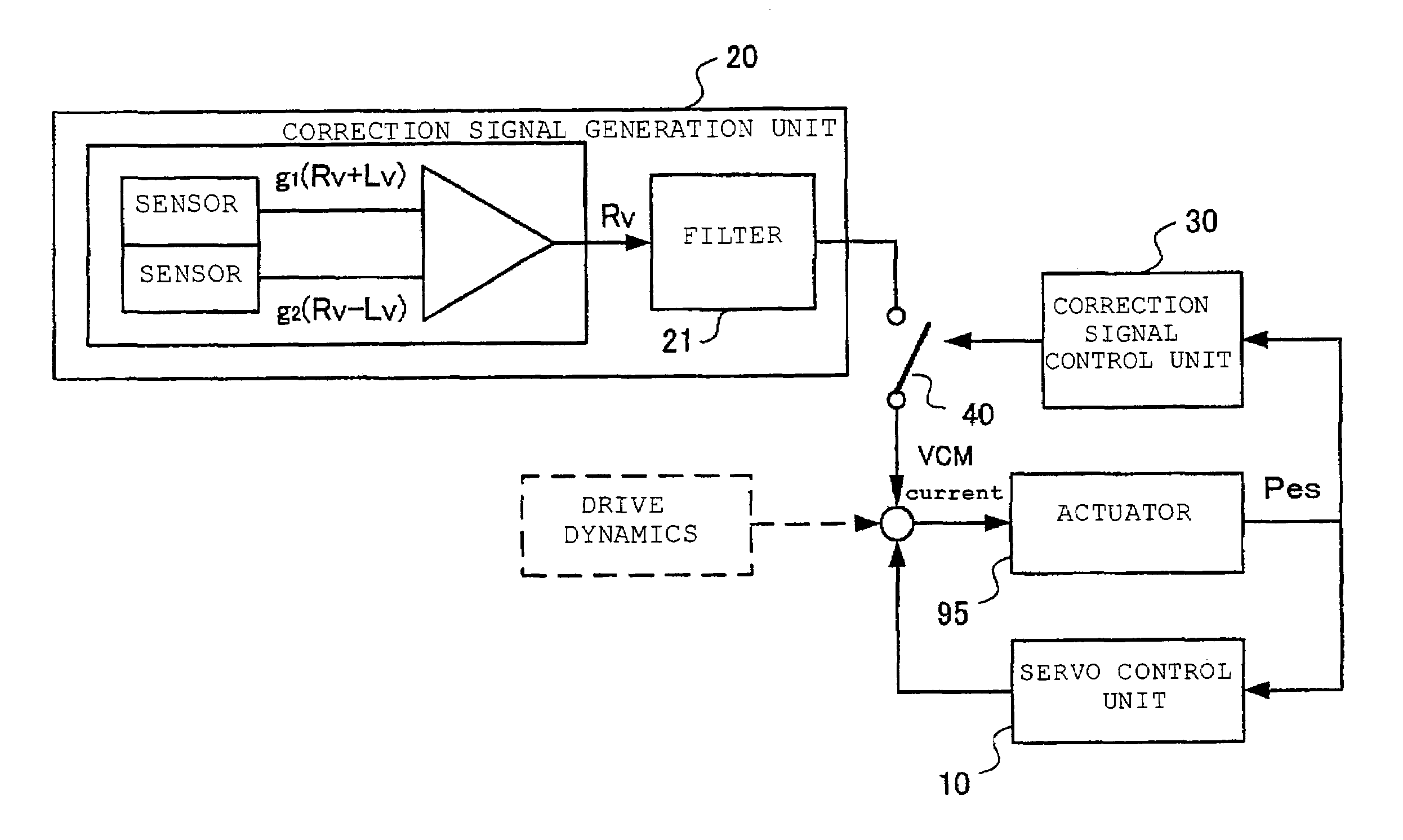
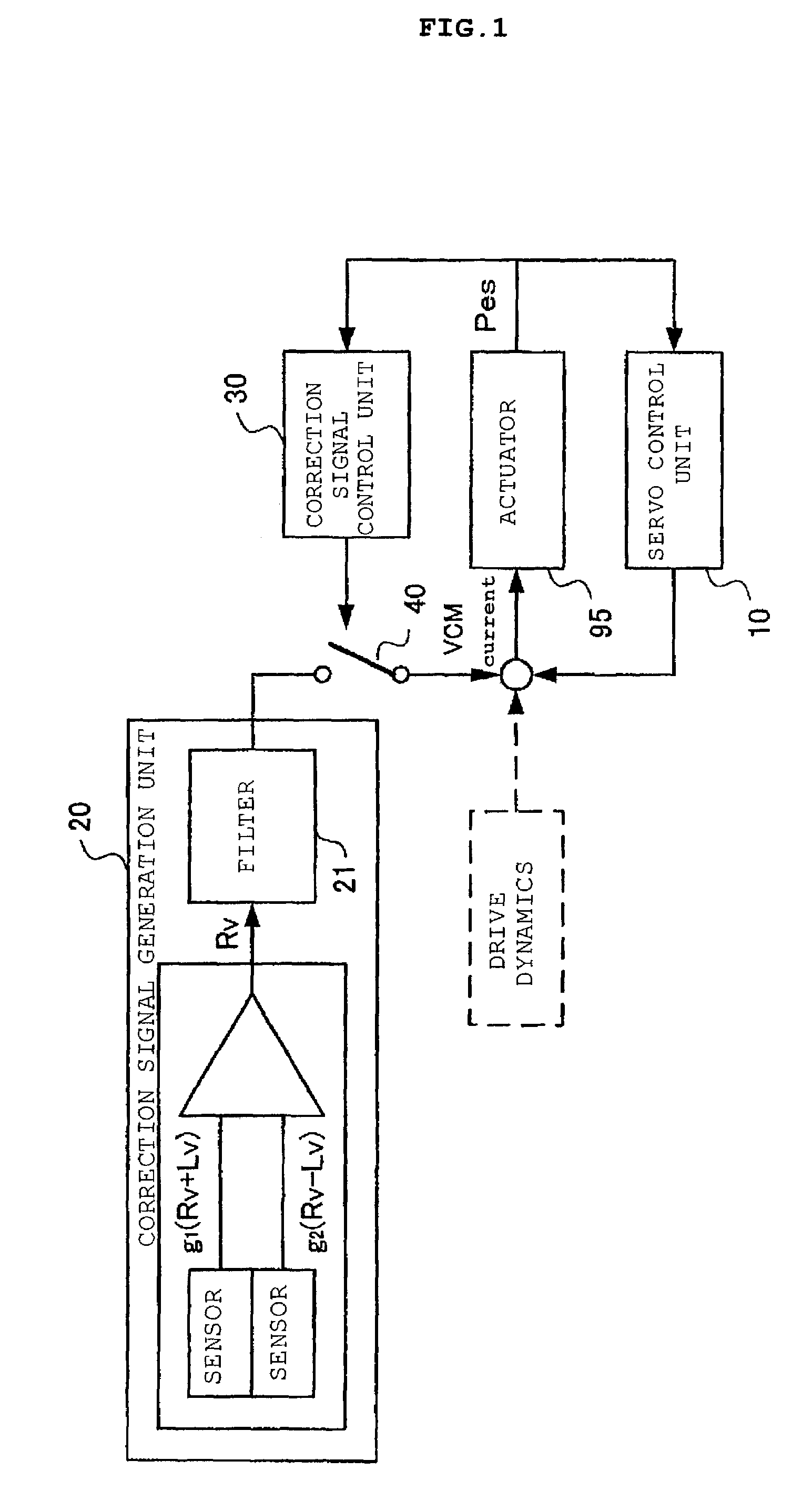
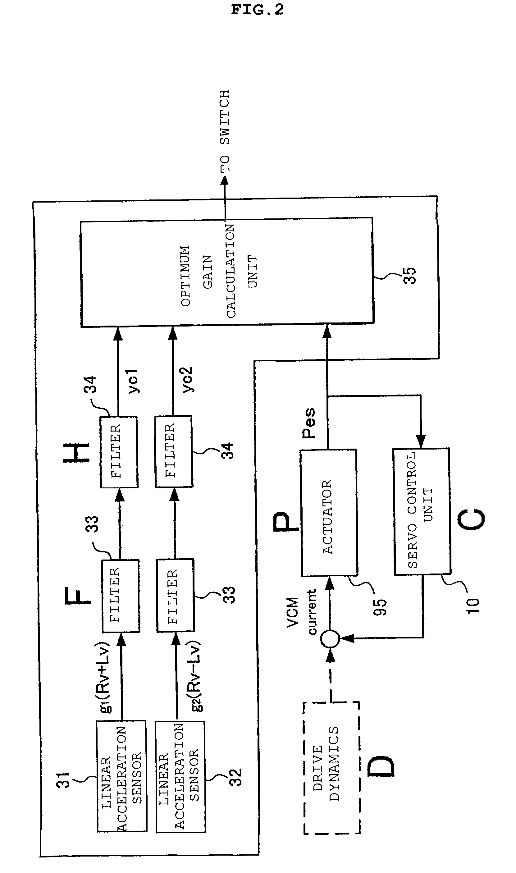
[0041]This embodiment monitors a signal of a sensor for detecting a vibration and a position signal of a head, and generates a correction signal that is a control signal for controlling an actuator so as to prevent the off-track of the head. Then, an effect obtained when this correction signal is added to a servo loop is estimated and evaluated, and a determination is dynamically performed based on the above estimation result as to whether or not the gain of the sensor should be changed or as to whether or not the correction signal should be added to the servo loop.

[0042]First, a hardware configuration of a general hard disk device will be described.

[0043]FIG. 9 is a block diagram showing principal portions of the hard disk device 91. The hard disk device 91 is a data storage / reproduction device, in which the magnetic heads 94 seek on the magnetic disk 92 rotationally d...


PUM


Abstract

A hard disk device includes a servo control unit that constitutes a servo loop for a head seek for performing read / write of data from / to a recording medium, a correction signal generation unit for generating a correction signal for correcting a control by the servo control unit based on an output of a predetermined sensor, and a correction signal control unit for estimating an effect of supplying the correction signal to the servo loop and for controlling whether or not the correction signal is to be supplied to the servo loop in response to a result of the estimation. Moreover, the gain of the sensor is dynamically controlled in response to the above estimation result.

Description

BACKGROUND OF THE INVENTION[0001]The present invention relates to a method for controlling a controlled system based on an output signal of a sensor, and more particularly, to a control method based on output signals of a plurality of sensors.[0002]In a data storage device (hereinafter, referred to as a “disk drive”) for recording data in a rotational recording medium such as a hard disk device, means for coping with off-track generated by vibrations is essential. For example, off-track becomes a problem when data recorded on a data-track other than a target data track is overwritten during data write. Therefore, a method exists, in which a sensor for vibration shocks is provided beforehand in the disk drive, and a control for interrupting to write data is performed in the case of detecting vibrations. Moreover, there is a method for controlling a head so as to follow the center of a track by adding a correction signal proportional to a vibration to a servo loop for an actuator of a...

Claims


Application Information

Patent Timeline
IPC IPC(8): G11B5/596G11B21/10G11B5/55
CPCG11B5/5582G11B5/5526
Inventor SEMBA, TETSUOKAGAMI, NAOYUKITOKIZONO, AKIRAIKEDO, GAKU
Owner HITACHI GLOBAL STORAGE TECH NETHERLANDS BV
Learn More