
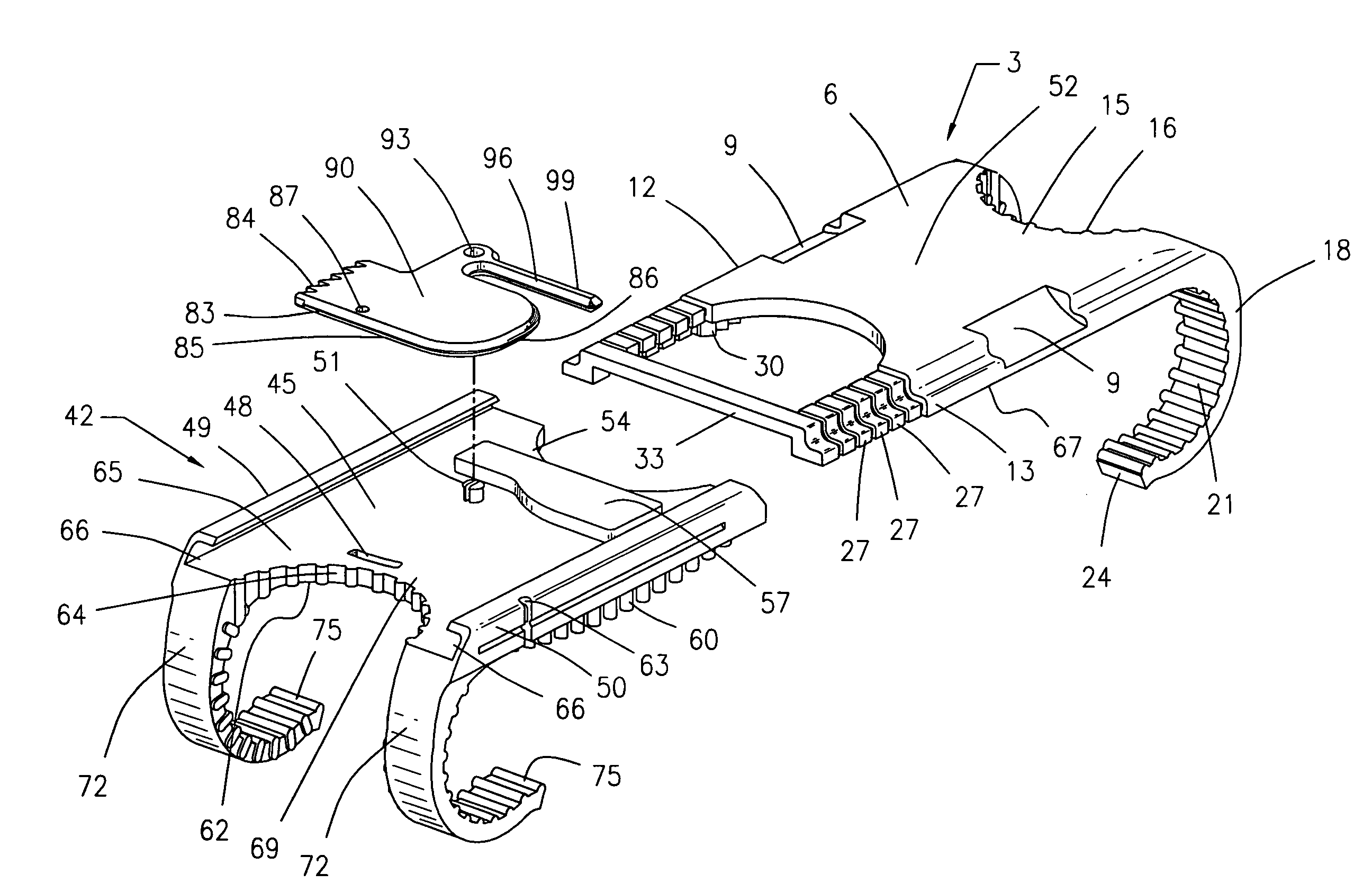
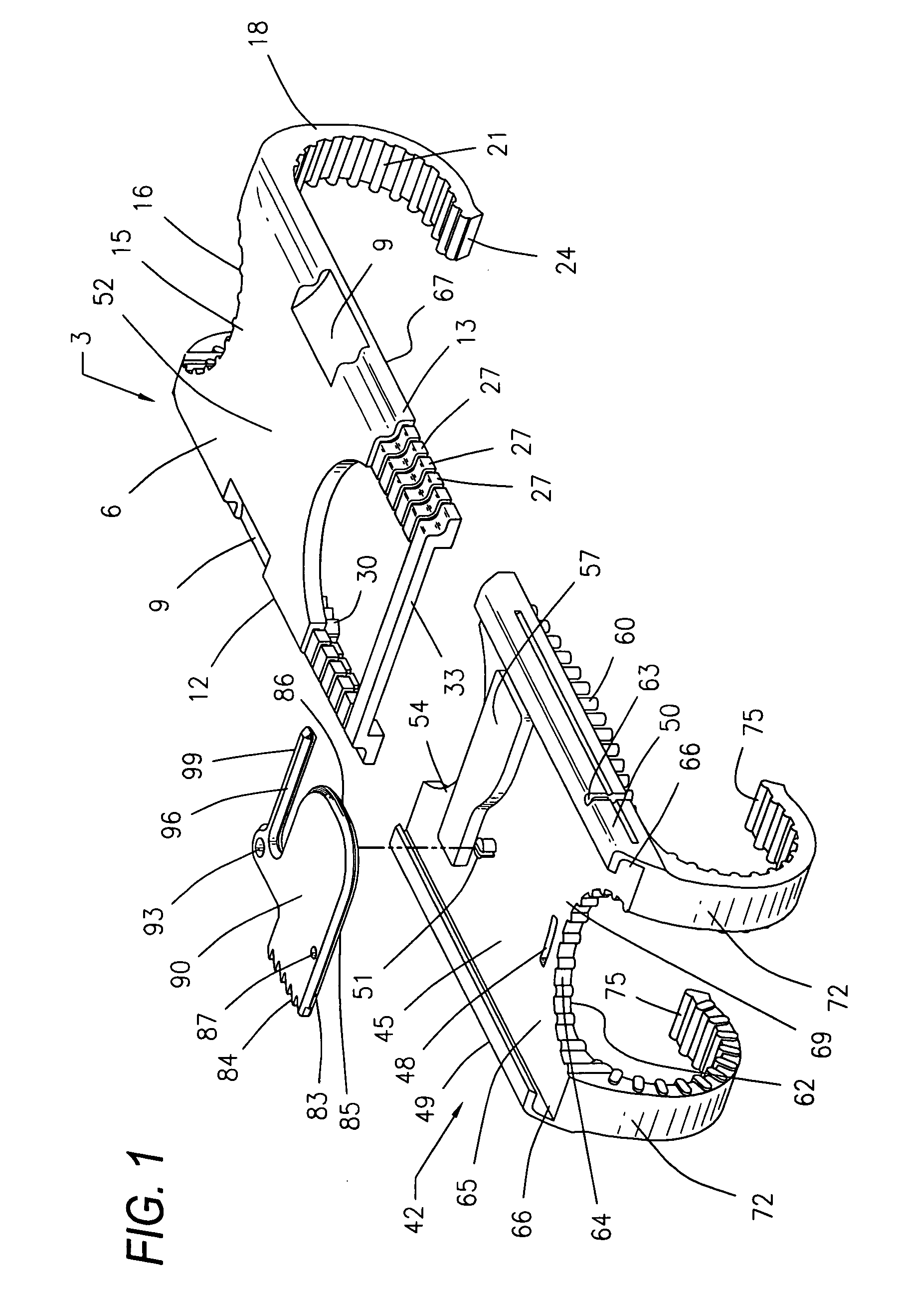
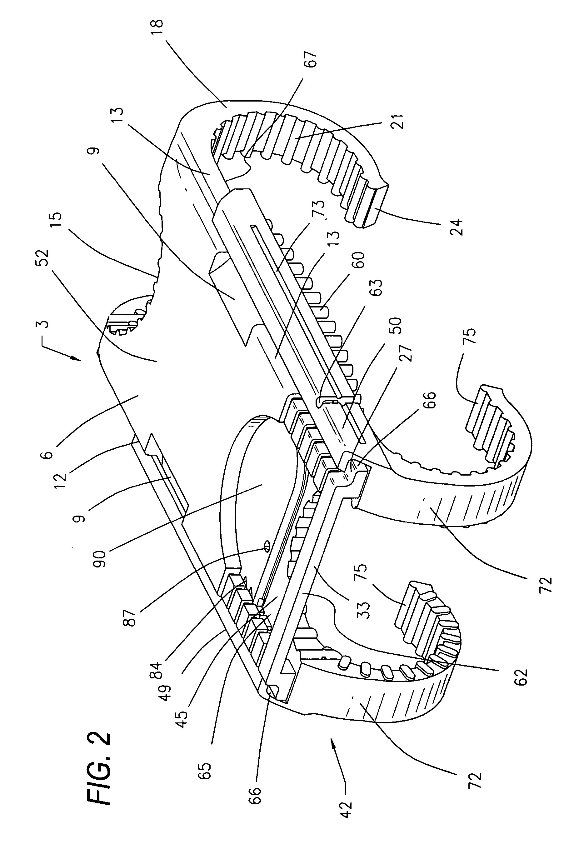
Surgical device for capturing, positioning and aligning portions of a severed human sternum

a surgical device and human sternum technology, applied in the direction of ligaments, osteosynthesis devices, prostheses, etc., can solve the problems of increasing operating room costs, time requirements, and continuing to be used with less than desirable, and achieve the effect of preventing rostral and vertical bone shearing travel

Active Publication Date: 2006-04-25
MAVREX MEDICAL LLC
View PDF9 Cites 89 Cited by
  • Summary
  • Abstract
  • Description
  • Claims
  • Application Information

AI Technical Summary

Benefits of technology

"The invention is a surgical device that helps capture, position, and align parts of a severed human sternum. It does this by surrounding the sternum with a device that prevents the two halves from moving relative to each other. The device has a unique design with insertion and guide attachment members that are permanently joined together. It also includes a rotary lock with teeth-like structures that work with reciprocating teeth-like structures on the guide member to securely position and combine the insertion member, guide, and rotary lock. Overall, the device helps improve the accuracy and precision of surgical procedures involving the sternum."

Problems solved by technology

Another example of a wire dependent closure system is marketed under Pectofix Surgical Technique Information with respect to deployment of this technique and its associated device can be found at the website http: / / www.pectofix.com / technique.shtm.Other wire closure systems are known to those skilled in the art, have been used in the past, and indeed continue to be used with less than desirable results.
Such an excessive time requirement translates, of course, into increased operating room costs, increased doctor, staff and insurance costs, and increased doctor fatigue.
All the afore-noted conditions result from inexact and undue stress conditions associated with wire closure devices in turn, and consistently result in slower patient discharges and unnecessary costs for the patient and community.
With respect to contemporary art wire based systems, such disruptive forces typically result in one or more of the following conditions: (a) wires cutting into bones; (b) sternal fragmentation; (c) broken wires; and (d) off-side sternotomy.
Though other clamp closure devices have been presented as effectuating an improvement over wire devices, no contemporary clamp closure provides the novel aspects and benefits afforded by the instant device for capturing, positioning and aligning portions of a severed human sternum via the device's unique structure for capturing and positioning the costal cartilage (notch) portion of each of a paired set of ribs located on opposite sides of a severed sternum while simultaneously contacting and substantially surrounding the anterior and posterior portions of the sternum and thereby preventing severed sternal halves from moving relative to one another and precluding rostral and vertical bone shearing travel.
Further and perhaps of greater importance, like the '007 patent, the '580 patent continues to present deficiency with respect to preventing rostral and vertical sheering of severed sternum halves in that it fails to capture or combine the positioning / securing benefits of aligning severed sternal halves in combination respective rib pair members.
Such positioning and structural dynamics render the Crossett device incapable of presenting the angularity offset required to evenly match and align the anterior portions of the severed sternum without inducing undue stress.
All resulting in lower risk to the patients, lower back end costs with lower post-op emergent returns, and indeed, lower overall hospital costs.

Method used


Image

  • Surgical device for capturing, positioning and aligning portions of a severed human sternum
  • Surgical device for capturing, positioning and aligning portions of a severed human sternum
  • Surgical device for capturing, positioning and aligning portions of a severed human sternum

Examples


Embodiment Construction

[0026]While making and using of various embodiments of the present invention are discussed in detail below, it should be appreciated that the present invention provides for inventive concepts capable of being embodied in a variety of specific contexts. The specific embodiments discussed herein are merely illustrative of specific manners in which to make and use the invention and are not to be interpreted as limiting the scope of the instant invention.

[0027]The claims and specification describe the invention presented and the terms that are employed in the claims draw their meaning from the use of such terms in the specification. The same terms employed in the prior art may be broader in meaning than specifically employed herein. Whenever there is a question between the broader definition of such terms used in the prior art and the more specific use of the terms herein, the more specific meaning is meant.

[0028]Referring now to the drawings wherein depicted elements are not necessaril...


PUM


Abstract

A surgical device for capturing, positioning and aligning portions of a severed human sternum via positioning around the costal cartilage portion of each of a paired set of ribs located on opposite sides of the severed sternum while simultaneously contacting and substantially surrounding the anterior and posterior portions of the sternum comprising impermanently joined insertion and insertion guide attachment members, each of the members having first and second end portions, first and second side portions, a body portion, anterior and posterior surfaces, two crescent formed leg portions with angularly displaced foot portions, a plurality of sternum, rib and costal cartilage engagement surfaces and, a rotary lock member pivotally attached to the insertion guide member, and further comprising a capturing mechanism having angularly displaced teeth-like structures on a first side cooperating with reciprocating teeth like structures integrated on a first side of the insertion member to position, secure in place and operatively combine the insertion member, rotary lock and insertion guide members.

Description

REFERENCE TO PENDING APPLICATIONS[0001]This application is not related to any pending application.REFERENCE TO MICROFICHE APPENDIX[0002]This application is not referenced in any microfiche appendix.FIELD OF INVENTION[0003]The present invention relates in general to surgical positioning devices and more particularly to a surgical device for capturing, positioning and aligning portions of a severed human sternum.BACKGROUND OF INVENTION[0004]Wire closures are widely represented in the contemporary art as a recognized means for closing the sternum following a mid-line sternotomy. Examples of such contemporary closure systems are marketed under a variety of device / methodology names including but not limited to the Hemostatic Sternal Closure® system which proclaims to be a major innovation based upon proven principals and cardiovascular surgery. At the time of this writing further documentation with respect to the Hemostatic Sternal Closure System may be found at the website http: / / www.al...

Claims


Application Information

Patent Timeline
Patent Type & Authority Patents(United States)
IPC IPC(8): A61B17/08A61B17/82A61B17/88A61F2/30
CPCA61B17/823A61B17/8076Y10S606/916A61B17/88
Inventor MILLER, III, ARCHIBALD S.
Owner MAVREX MEDICAL LLC
Learn More