Actuating device of wrist exerciser

a wrist exerciser and wrist technology, applied in the field of wrist exercisers, can solve the problems of loss of control of the rotor ab>1/b>, failure of initial rotation, and potential risks to the finger of the player, and achieve the effect of high rotational speed

Active Publication Date: 2006-04-25
CHUANG YUN YU +2
View PDF7 Cites 22 Cited by
  • Summary
  • Abstract
  • Description
  • Claims
  • Application Information

AI Technical Summary

Benefits of technology

[0009]An object of the present invention is to provide a wrist exerciser having an actuating device that can be readily operated with no failure in initially starting the wrist exerciser.
[0010]Another object of the present invention is to provide a wrist exerciser comprising a casing having no large opening for the extension of a driving rope whereby damage caused by accidentally placing a finger into the casing by the player can be effectively eliminated.

Problems solved by technology

Thus, when the rope B is quickly pulled off the rotor A1, the force that pulls the rope B off the rotor A1 may cause deviation of the rope B from the desired moving direction and thus leading to lose of control of the rotor A1 and failure of initial rotation.
In addition, since there must be an opening A21 defined in the casing for the extension of the rope B, surface integration of the spherical casing cannot be maintained, causing undesired adverse effect on the playing of the wrist exerciser A. The opening A21 may cause potential risks to the player's finger if the player accidentally puts his or he finger into the casing through the opening A21 and hit by the rotor A1 that is rotating in high speed.

Method used


Image

  • Actuating device of wrist exerciser
  • Actuating device of wrist exerciser
  • Actuating device of wrist exerciser

Examples


Embodiment Construction

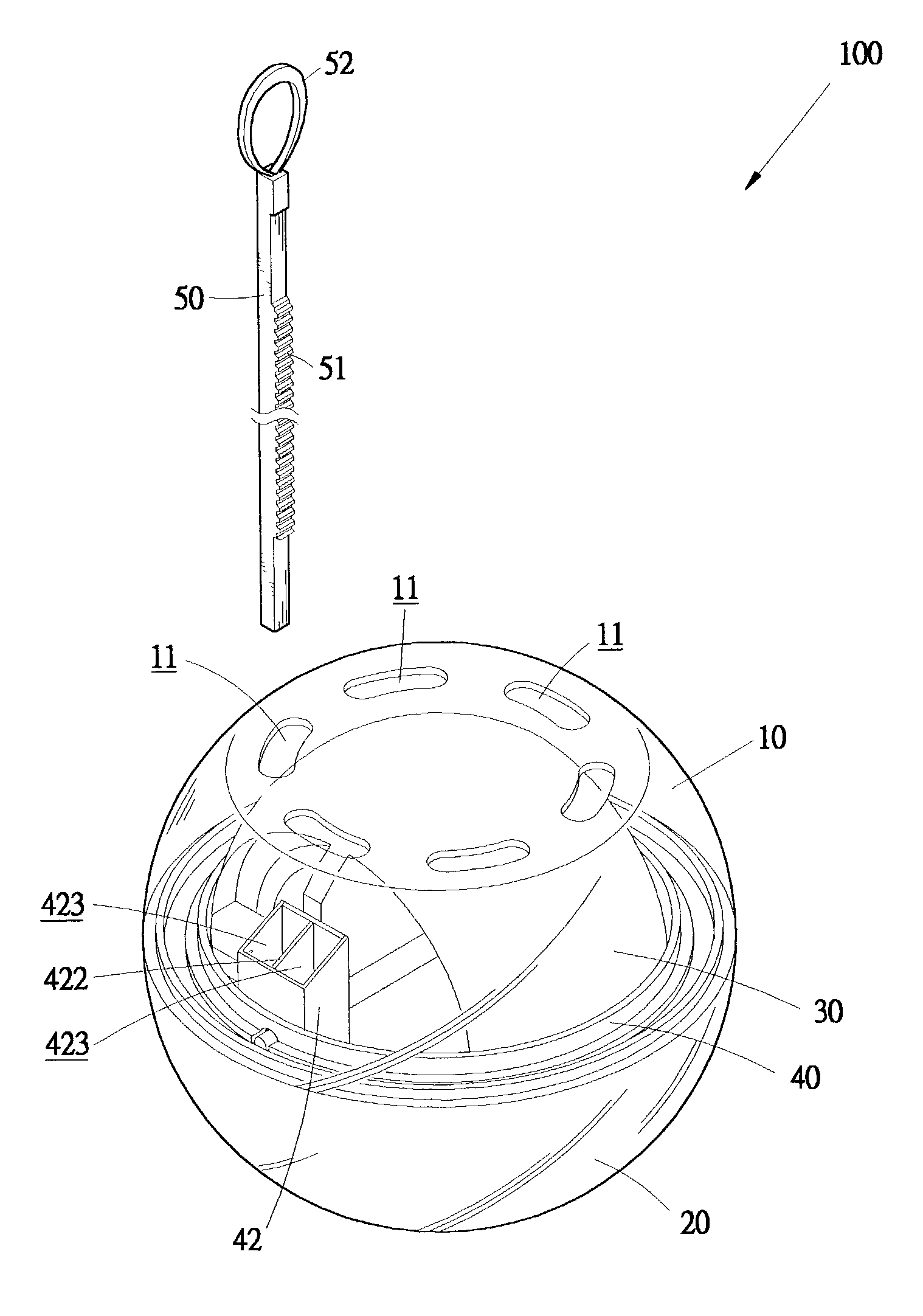
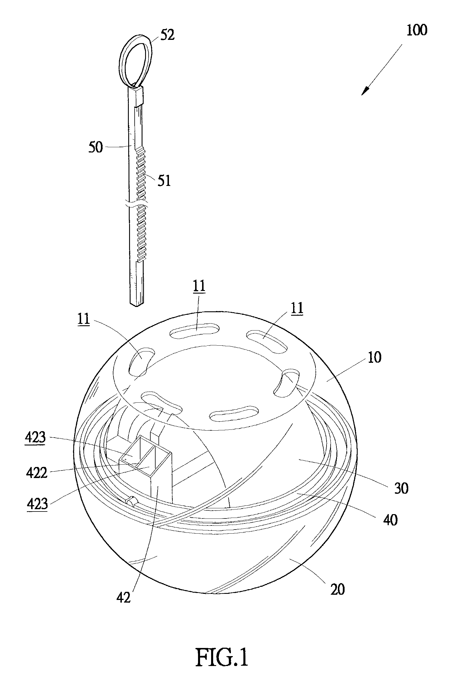
[0024]With reference to the drawings and in particular to FIGS. 1–4, a wrist exerciser constructed in accordance with the present invention, generally designated with reference numeral 100, comprises a casing having a substantially spherical shape and comprising upper and lower casing members 10, 20 mating each other to define an interior space (not labeled) therebetween. If desired, the upper and lower casing members 10, 20 may be movable relative to each other A spherical rotor 30 is rotatably supported and received in the interior space. Slots 11, 12, preferably elongated in a circumferential direction, are defined in the upper and lower casing members 10, 20 and substantially aligned with each other.

[0025]A support ring 40 is mounted between the upper and lower casing members 10, 20 and defines diametrically opposite holes 41. The rotor 30 comprises a substantially spherical body having axially aligned rotation shafts 32 on opposite sides thereof for being rotatably received in ...


PUM


Abstract

A wrist exercise includes a casing rotatably receiving a rotor therein. The casing defines slots that are aligned in pair. The rotor has axially aligned rotation shafts respectively and rotatably received in holes defined in the casing for rotatably supporting the rotor inside the casing. A drive roller is mounted to one of the rotation shafts. A drive bar is partially and movable received in the casing through the aligned slots to drivingly engage the drive roller whereby by forcibly pulling the drive bar out of the casing, the drive roller is caused to drive an initial rotation of the rotor with a high rotational speed.

Description

BACKGROUND OF THE INVENTION[0001]1. Field of the Invention[0002]The present invention generally relates to a wrist exerciser, and in particular to the initial actuation of the wrist exerciser.[0003]2. The Related Art[0004]Wrist exercisers comprising a hollow casing inside which a spherical rotor is rotatably supported are known for exercising wrist-related muscles and for rehabilitation purposes. An example of the wrist exerciser is shown in U.S. Pat. No. 5,800,311. The operation of the wrist exerciser starts with actuating and driving the rotor to have the rotor rotating in high speed with great torque. A player that plays the wrist exerciser then uses his or her wrist and palm muscles to maintain the rotation of the rotor. This exercises the palm and wrist muscles of the player. In this respect, the initial actuation of the rotor is of importance.[0005]FIG. 10 of the attached drawings shows a conventional wrist exerciser, generally designated with reference numeral A. The wrist ex...

Claims


Application Information

Patent Timeline
IPC IPC(8): A63B23/14A63B43/06A63B21/22
CPCA63B21/22A63B21/00061A63B23/03508A63B23/14A63B2021/222A63B21/222
Inventor CHUANG, YUN YULIN, MING HUNGCHUANG, PEI SUNG
Owner CHUANG YUN YU
Why Eureka
Try Eureka