
Method and apparatus for assessing performance of an environmental control system

a technology of environmental control system and performance assessment, applied in the field of environmental control system, can solve problems such as poor control response, difficulty in maintaining the precise control of the controlled variable, and affecting the accuracy of the control variable,

Active Publication Date: 2006-04-18
JOHNSON CONTROLS TECH CO
View PDF35 Cites 321 Cited by
  • Summary
  • Abstract
  • Description
  • Claims
  • Application Information

AI Technical Summary

Benefits of technology

[0013]The present invention relates to a method and apparatus for assessing performance of an environmental control network. The

Problems solved by technology

With any of the forgoing feedback control strategies, however, it can be difficult to maintain the controlled variable precisely at the desired set point for various reasons, including that the appropriate values for the control parameters may change over time as the system is used.
For example, the dynamics of a process may be altered by heat exchanger fouling, inherent nonlinear behavior, ambient variations, flow rate changes, large and frequent disturbances, and unusual operations status such as failures, startup and shutdown.
If a controller is not periodically retuned, the control response may become poor.
For example, the controlled variable may become unstable or oscillate widely with respect to the setpoint.
This can result in inefficient operation as well as increase the maintenance costs due to unnecessary wear of the components.
However, human operators must typically select the thresholds for alarms and warnings, which can be a daunting task.
If the thresholds are too tight, numerous false alarms may be issued.
Conversely, if the thresholds are too loose, equipment or system failures can go undetected.

Method used


Image

  • Method and apparatus for assessing performance of an environmental control system
  • Method and apparatus for assessing performance of an environmental control system
  • Method and apparatus for assessing performance of an environmental control system

Examples


Embodiment Construction

[0028]The particulars shown herein are by way of example and for purposes of illustrative discussion of the embodiments of the present invention only and are presented in a manner that is believed to provide the most useful and readily understood description of the principles and concepts of the present invention. In this regard, no attempt is made to show structural details of the present invention in more detail than is necessary to provide a fundamental understanding of the present invention. The description of the invention taken with the drawings is believed sufficient to make it apparent to those skilled in the art how several forms of the present invention may be embodied in practice.

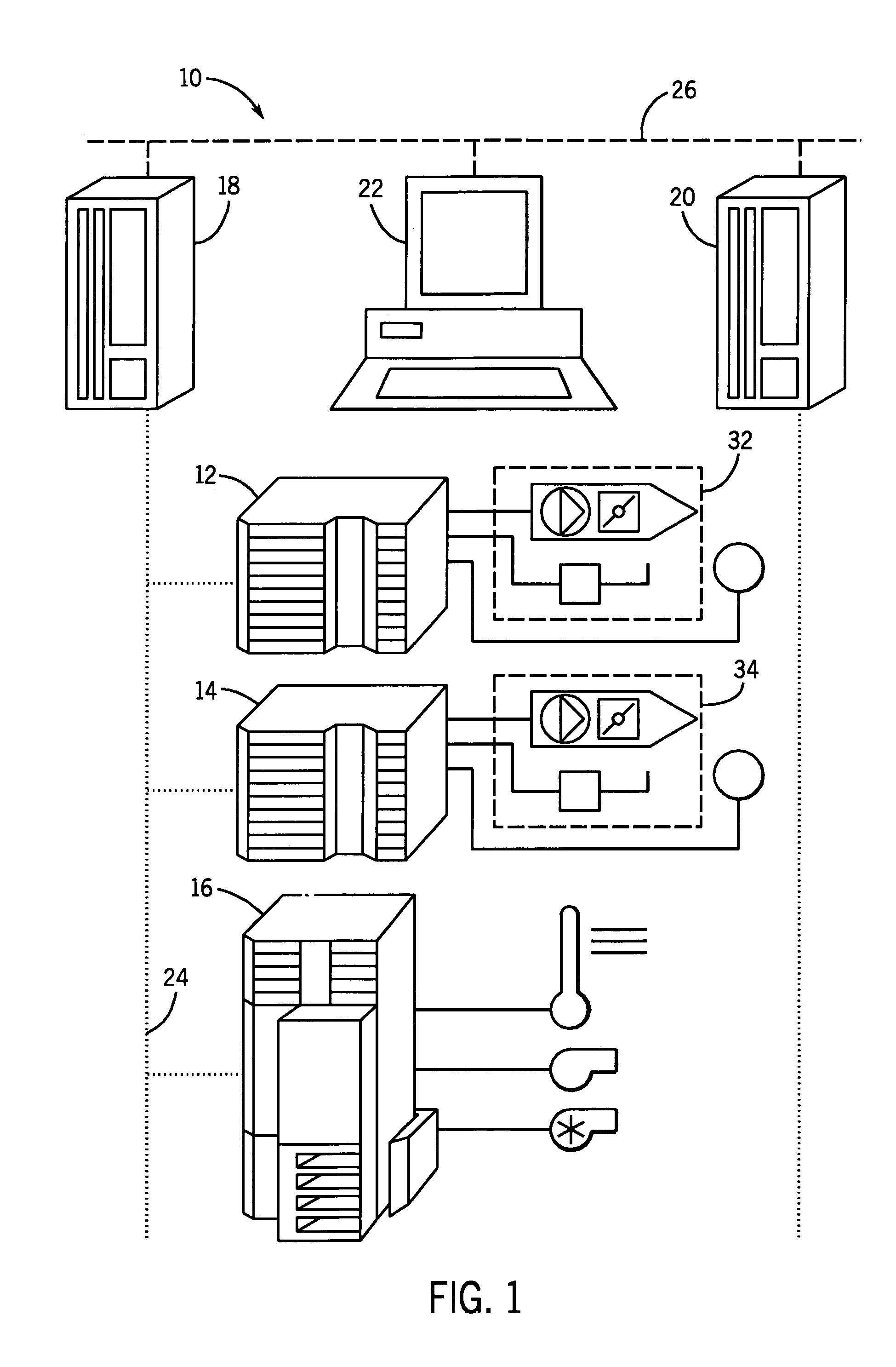
[0029]Turning now to the drawings and referring initially to FIG. 1, an environment control system or network 10 includes a plurality of field controllers 12, 14 and 16, a pair of supervisory controllers 18 and 20, and a work station 22. Field controllers 12, 14 and 16 may be coupled to each othe...


PUM


Abstract

A method and apparatus is disclosed for assessing performance of control applications in an environmental control network and for diagnosing performance problems. The apparatus includes a performance assessment and diagnostic display comprising a facility navigation tree, a system navigation tree and a performance / diagnostics window. The facility navigation tree and system navigation tree may be used to select the facilities and systems that are to have their associated control applications assessed and / or diagnosed. The performance / diagnostics window includes graphs of performance indictors that are indicative of performance levels for the included control applications. The system tree may be used to delve to more detailed views of the performance indicators to obtain additional information that may help to diagnose problems noted in performance of the selected control applications.

Description

FIELD OF THE INVENTION[0001]The present invention relates to an environmental control system. More particularly, the present invention relates to a method and apparatus for assessing performance of environmental control networks. The present invention also relates to a method and apparatus for diagnosing performance problems in environmental control networks.BACKGROUND OF THE INVENTION[0002]Environmental control networks or facility management systems are employed in office buildings, manufacturing facilities, and the like, for controlling the internal environment of the facility. The environmental control network may be employed to control temperature, fluid flow, humidity, lighting, boilers, chillers, power, security and similar systems in the internal environment.[0003]For example, in environmental control networks configured to control temperature and air flow, controlled air units such as variable air volume (VAV) boxes and unitary devices (UNT) are located throughout the facil...

Claims


Application Information

Patent Timeline
IPC IPC(8): G06F19/00
CPCG05B23/0232G05B23/0216
Inventor SEEM, JOHN E.HUTH, WILLIAM A.FRAUNE, ROBERT J.LEWIS, ANITA M.KY, TRI V.
Owner JOHNSON CONTROLS TECH CO
Learn More