
Dynamic computing imagery, especially for visceral osteopathy and for articular kinetics

a dynamic computing and imaging technology, applied in the field of visceral osteopathy and articular kinetics, can solve the problems of unavoidable picking error, difficult task of picking points on the boundary, and inability to accurately identify the boundary, so as to avoid deformation or further deformation of the shape

Inactive Publication Date: 2006-04-11
WILLIAME CHRISTIAN +1
View PDF8 Cites 18 Cited by
  • Summary
  • Abstract
  • Description
  • Claims
  • Application Information

AI Technical Summary

Problems solved by technology

After analysing around 3000 images by a filly manual procedure, results of which is partly published in reference [1], it appears that this manual approach is in any case too much time consuming for application daily life.
The correct picking of points on the boundary is a difficult task and error of picking is unevitable.
Such a step requires time and accurateness from the user.
When using such a method for analysing the movement of bones, the results of the analysis are subjective (dependent from the doctor making the analysis) and its accurateness is low.
The main difficulty in the treatment of a vision application is the lack of general theory or universal method offering the answer to several problems at the same time.
For example, in order to examine the surface quality of continuous plane, products on a high-speed production line cannot be used for recognition of characters or for medical diagnosis.
This requires a certain knowledge from the operator about the clinical problem and is expected to consume much time for a significant result.
This method is not desirable in the processing of large data set and its reproducibility is reduced.
Completely automatic: the available techniques presented for automatic contouring are not yet enough sophisticated for many typical applications.
This approach is very time consuming and the results are not reproducible.

Method used


Image

  • Dynamic computing imagery, especially for visceral osteopathy and for articular kinetics
  • Dynamic computing imagery, especially for visceral osteopathy and for articular kinetics
  • Dynamic computing imagery, especially for visceral osteopathy and for articular kinetics

Examples


Embodiment Construction

[0086]The method of the invention is operated by a computer or by computers connected there between directly (internet, extranet, intranet, local provider, communication means, etc.) or indirectly (by means of electronic support means, disc, Cdrom, etc.). Preferably, the computerized method is carried out on a local computing system, such as on a personal computer, laptop, etc.

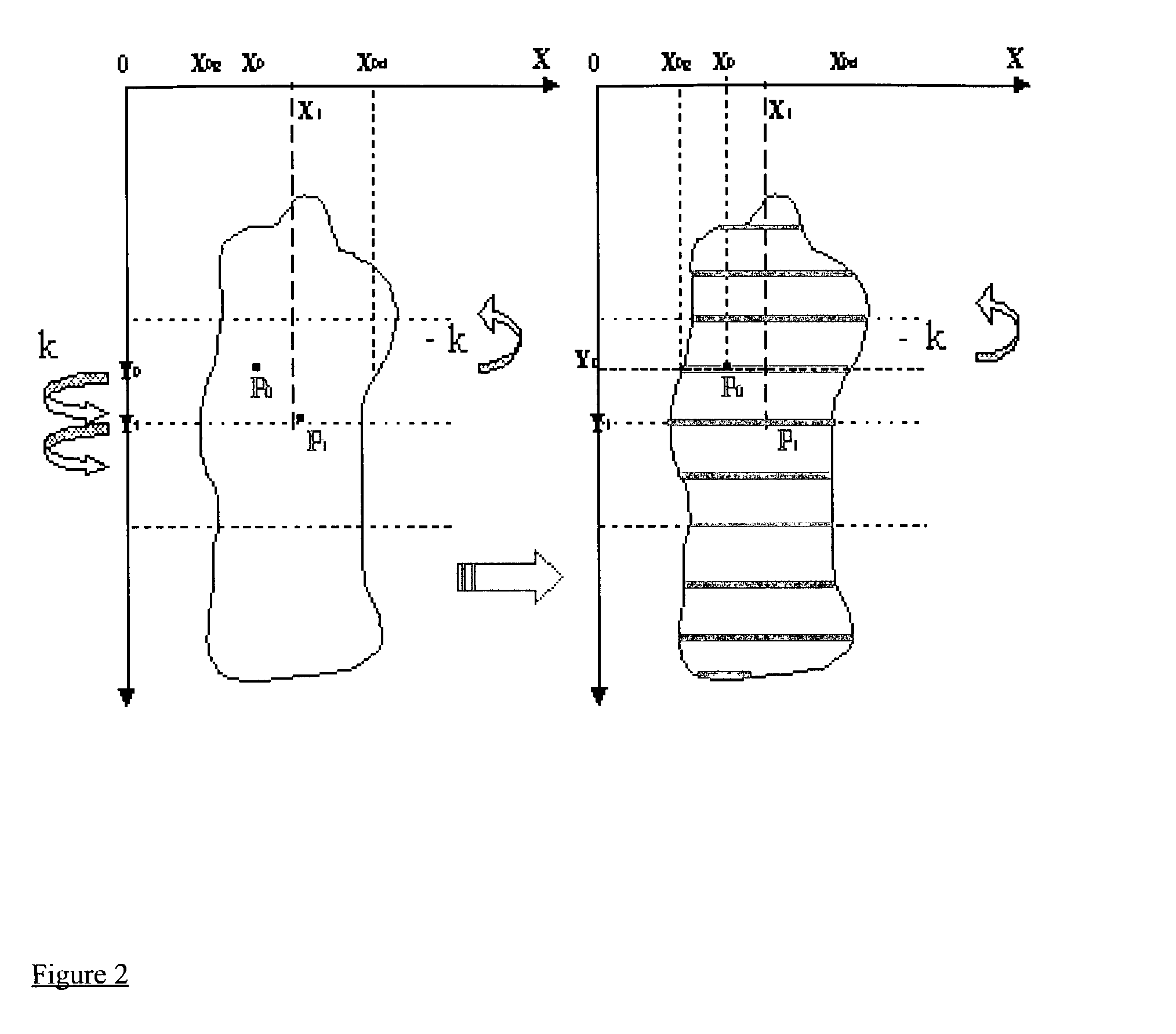
[0087]A preferred method will now be described for analysing the alterations in the location of a viscera in the inhalation position (image 1) and in the exhalation position (image 2).

[0088]The computer is operating the method as follows, as shown schematically in FIG. 1:

Image Capturing

[0089]Two images of the viscera in extreme positions are converted in numerical forms, so as to enable the further processing thereof.

[0090]In the present case, the image capturing system used was a scanner suitable for converting paper image 1 and paper image 2 into a numerical forms readable by the computer for the further tre...


PUM


Abstract

Computerized method for studying alterations in the location of an object, said method comprising the steps of computing successive shapes by means of a dynamic contour model algorithm, whereby the dynamic contour model algorithm develops successive shapes and determines a correlation between two successive shapes and for stopping the reiteration of the algorithm when said determined correlation is lower than a predetermined value.

Description

[0001]This application is a continuation-in-part of co-pending International Application No. PCT / BE00 / 00145, with an international filing date of Dec. 8, 2000, published in English under PCT Article 21(2) on Jun. 14, 2001 which claims the benefit of U.S. Provisional Application No. 60 / 170,222 filed Dec. 10, 1999.FIELD OF THE INVENTION[0002]The present invention is related to a computing imagery method for studying alterations in the location of an object after a movement thereof. In said method, the position of the object in two images is analyzed. This method is particularly suitable for evaluating or controlling visceral movement or articular kinetics based on medical imaging techniques. The invention is equally related to a computer program for performing said method.THE PRIOR ART[0003]It has already been proposed to analyze two images of an object so as to determine the movement of said object between its position in the first image and its position in its second image.[0004]Suc...

Claims


Application Information

Patent Timeline
Patent Type & Authority Patents(United States)
IPC IPC(8): G06K9/62G06K9/00G06K9/46G06T7/20
CPCG06K9/6207G06T7/2046G06K2209/051G06T2207/30004G06T2207/10116G06T7/251G06V10/755G06V2201/031
Inventor WILLIAME, CHRISTIANFINET, GEORGES
Owner WILLIAME CHRISTIAN
Learn More