Antenna apparatus having high receiving efficiency
a technology of antenna apparatus and receiving efficiency, which is applied in the direction of resonant antenna, substantially flat resonant elements, polarised antenna unit combinations, etc., can solve the problems of difficult to receive radio signals having different polarization planes, narrow directivity of built-in antenna apparatus, and difficult to obtain desirable antenna characteristics for mobile telephones. , to achieve the effect of high receiving efficiency
- Summary
- Abstract
- Description
- Claims
- Application Information
AI Technical Summary
Benefits of technology
Problems solved by technology
Method used
Image
Examples
first embodiment
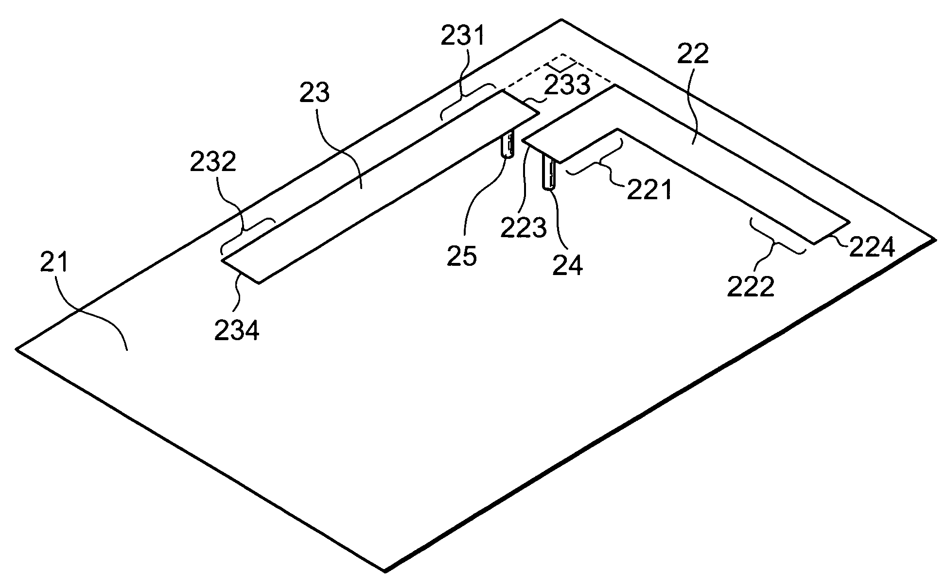
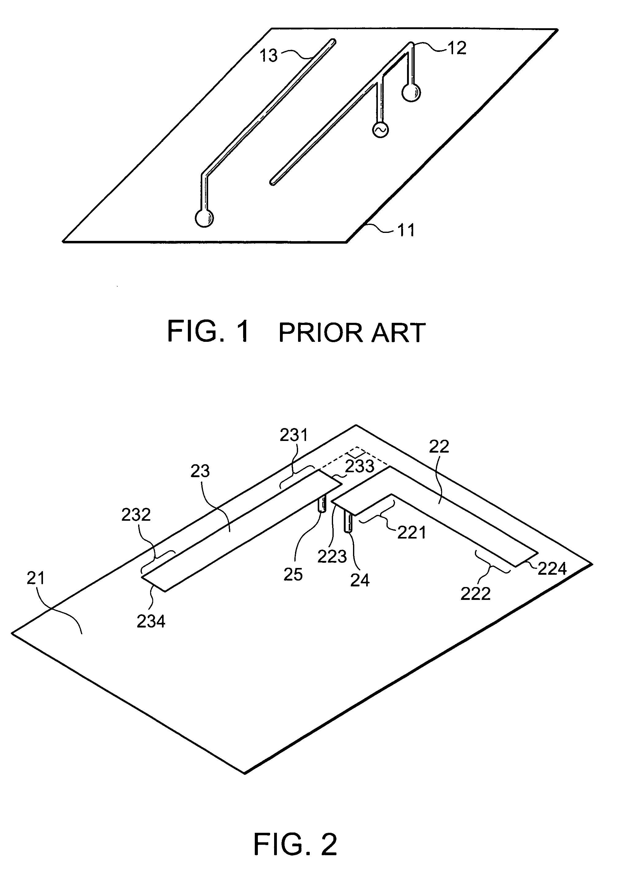
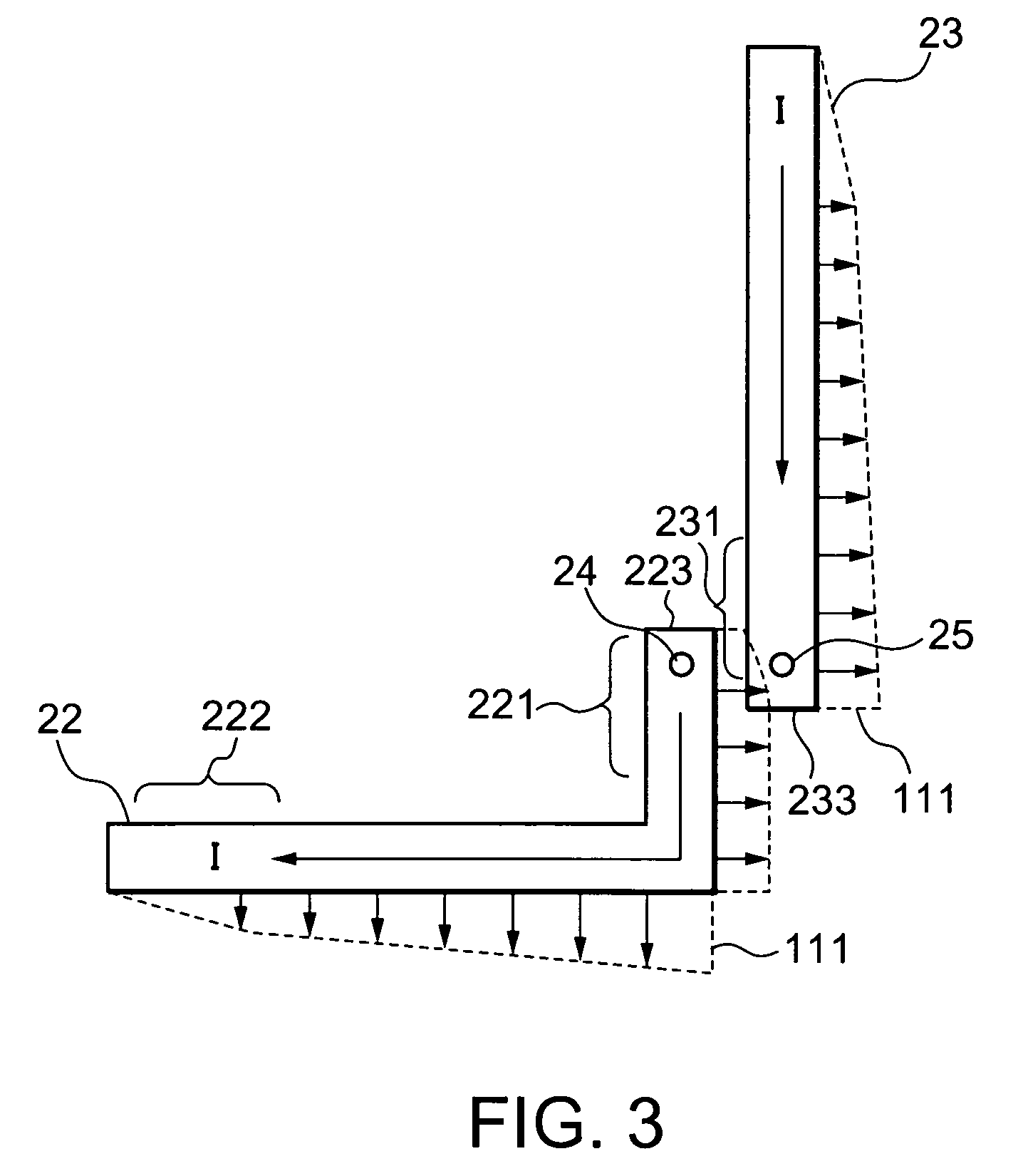
[0021]Referring to FIGS. 2 to 4, the description will be proceed to an antenna apparatus according to this invention.
[0022]FIG. 2 is a schematic perspective view of the antenna apparatus. As illustrated in FIG. 2, the antenna apparatus comprises a conductive plate 21, a main antenna line element 22 and a parasitic antenna line element 23. The antenna line elements 22 and 23 are located above the conductive plate 21 to be substantially parallel to the conductive plate 21.
[0023]The main antenna line element 22 comprises an L shaped thin metal plate with first and second end portions 221 and 222. The first and second end portions 221 and 222 include longitudinal edges 223 and 224 and extend in different directions which are substantially perpendicular to each other. The first end portion 221 provides a feeding point which is connected to a radio transmitter / receiver circuit (42 of FIG. 4A) mounted on the conductive plate 21 with a feeding terminal 24. The feeding point is close to the ...
second embodiment
[0032]FIG. 5 is a schematic perspective view of an antenna apparatus according to this invention. Similar parts are designated by the same reference numerals.
[0033]The antenna apparatus is similar to that of first embodiment except a resin member 51. That is, the antenna apparatus of FIG. 5 comprises the conductive plate 21, the main antenna line element 22, the parasitic antenna line element 23 and the resin member 51.
[0034]The resin member 51 unifies the main antenna line element 22 and the parasitic antenna line element 23 to maintain relative arrangement between the main antenna line element 22 and the parasitic antenna line element 23. That is, the resin member 51 maintains a distance between the main antenna line element 22 and the parasitic antenna line element 23 and impedance of them. Furthermore, the resin member 51 prevents both the main antenna line element 22 and the parasitic antenna line element 23 from being deformed. This makes assembling the antenna apparatus easy....
third embodiment
[0035]FIG. 6 is a schematic perspective view of an antenna apparatus according to this invention.
[0036]The antenna apparatus comprises a main antenna line element 22a. The main antenna line element 22a has a total length shorter than that of the main antenna line element 22 of FIG. 2 or 5. The main antenna line element 22a is grounded to the conductive plate 21 with a grounding terminal 61. The grounding terminal 61 is connected to the first end portion 233 together with a feeding terminal 24a. The grounding terminal 61 is closer to the longitudinal edge 233 than the feeding terminal 24a. With this structure, the shorter length of the main antenna line element 22a makes it possible to miniaturize the whole of the antenna apparatus.
[0037]FIG. 7 is a schematic perspective view of an antenna apparatus according to a forth embodiment of this invention.
[0038]The antenna apparatus has no grounding terminal connected to the parasitic antenna line element. In other words, both of the third ...
PUM
 Abstract
Description
Claims
Application Information
 - R&D
- Intellectual Property
- Life Sciences
- Materials
- Tech Scout
- Unparalleled Data Quality
- Higher Quality Content
- 60% Fewer Hallucinations
Browse by: Latest US Patents, China's latest patents, Technical Efficacy Thesaurus, Application Domain, Technology Topic, Popular Technical Reports.
© 2025 PatSnap. All rights reserved.Legal|Privacy policy|Modern Slavery Act Transparency Statement|Sitemap|About US| Contact US: help@patsnap.com


