
Rope gasket with termination

a technology of rope gaskets and ropes, which is applied in the direction of lighting and heating apparatus, heating types, and domestic stoves or ranges. it can solve the problems of reducing the aesthetic appeal of the gasket and its effectiveness, affecting the performance of the gasket, and affecting the effect of the gasket at the join

Inactive Publication Date: 2006-04-11
DAVLYN MFG
View PDF25 Cites 5 Cited by
  • Summary
  • Abstract
  • Description
  • Claims
  • Application Information

AI Technical Summary

Benefits of technology

"The invention is a gasket made of rope made of fibrous glass yarns with two free ends. These ends are brought together to form a joint, and a termination sleeve is placed around the joint to make sure it is soft and fits snugly around the rope. This results in a gasket that is flexible and can conform to the shape of the rope at the joint."

Problems solved by technology

Typical rope gaskets are problematic at the location where the two ends of the rope meet to form a joint and make the gasket a loop.
Some gaskets do not have any termination device to help secure the joint formed by bringing the ends of the rope gasket together.
This often results in fraying of the rope at the joint that lessens aesthetical appeal of the gasket and its effectiveness as a sealing device.
The absence of a termination device around the joint also results in a weak joint that can break apart and make the gasket discontinuous at the joint.
Some known devices include a termination part that helps secure the joint, but these known termination parts have encountered several problems.
The materials used to conceal the joint have tended to cause a lump at the joint and have burned due to the high operating temperatures.
Lumping and burning at the joint results in a less effective seal.
Additionally, typically the termination parts have not conformed to the shape of the joint.
In these known termination parts that cannot be manipulated to tightly conform to the shape of the joint there is still a possibility of fraying.
Termination parts that do not conform to the shape of the gasket also tend to cause an irregularity of shape at the joint, making it more difficult to create an effective installation and seal with the gasket.

Method used


Image

  • Rope gasket with termination
  • Rope gasket with termination

Examples


Embodiment Construction

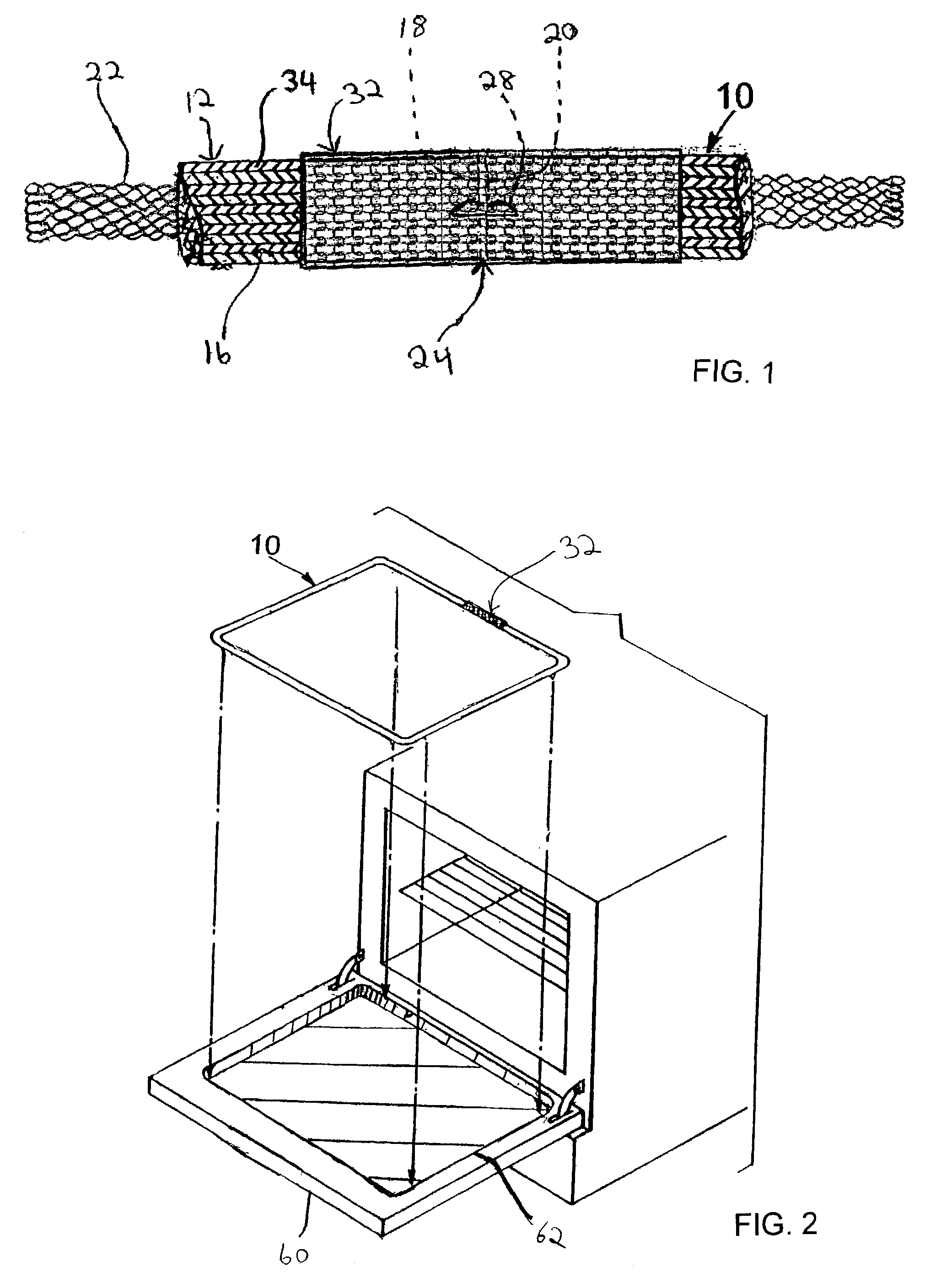
[0007]Referring to the drawings in detail, like numerals are employed for the indication of like elements throughout. There is shown in FIGS. 1–2, indicated generally at 10, a preferred embodiment of a continuous or closed loop rope gasket of the present invention with termination sleeve, suitable for providing cushioning and a seal around windows used in high temperature devices such as the glass window used in an oven. The gasket 10 is primarily intended to seal in heat, smoke, and vapors. Referring specifically to FIG. 1 the gasket 10 primarily comprises a length of rope 12 with at least two free ends 18, 20, a joint 24 formed by bringing together the two free ends 18, 20 of rope 12, a termination sleeve 32 surrounding the joint 24, and an attachment device 28 to both attach the free ends 18, 20 to each other to form the joint 24 and the termination sleeve 32 to the rope 12 overlapping the joint 24 where the free ends 18, 20 meet, to form the closed or continuous loop of gasket 1...


PUM


Abstract

The present invention is a gasket comprising a length of rope formed at least substantially by a plurality of interwoven fibrous glass yarns and having at least two ends, and a soft wire mesh termination sleeve placed around and attached to the rope member at the joint that conforms to the shape of the gasket joint.

Description

BACKGROUND OF THE INVENTION[0001]Interwoven fibrous rope gaskets are often used for sealing and cushioning around windows used in devices that operate at high temperatures such as the glass window of an oven. Typical rope gaskets are problematic at the location where the two ends of the rope meet to form a joint and make the gasket a loop. Some gaskets do not have any termination device to help secure the joint formed by bringing the ends of the rope gasket together. This often results in fraying of the rope at the joint that lessens aesthetical appeal of the gasket and its effectiveness as a sealing device. The absence of a termination device around the joint also results in a weak joint that can break apart and make the gasket discontinuous at the joint. Some known devices include a termination part that helps secure the joint, but these known termination parts have encountered several problems. The materials used to conceal the joint have tended to cause a lump at the joint and h...

Claims


Application Information

Patent Timeline
Patent Type & Authority Patents(United States)
IPC IPC(8): F16J15/02F16J15/06F16J15/08F16J15/22F24C15/02
CPCF16J15/065F24C15/021F16J15/22F16J15/0812D10B2101/06D10B2101/20D10B2505/06D04B1/225D04C1/06
Inventor FLASHER, GARY L.
Owner DAVLYN MFG
Learn More