Process and apparatus for treating a feed gas
Inactive Publication Date: 2006-04-04
AIR PROD & CHEM INC
View PDF22 Cites 20 Cited by
- Summary
- Abstract
- Description
- Claims
- Application Information
AI Technical Summary
Benefits of technology
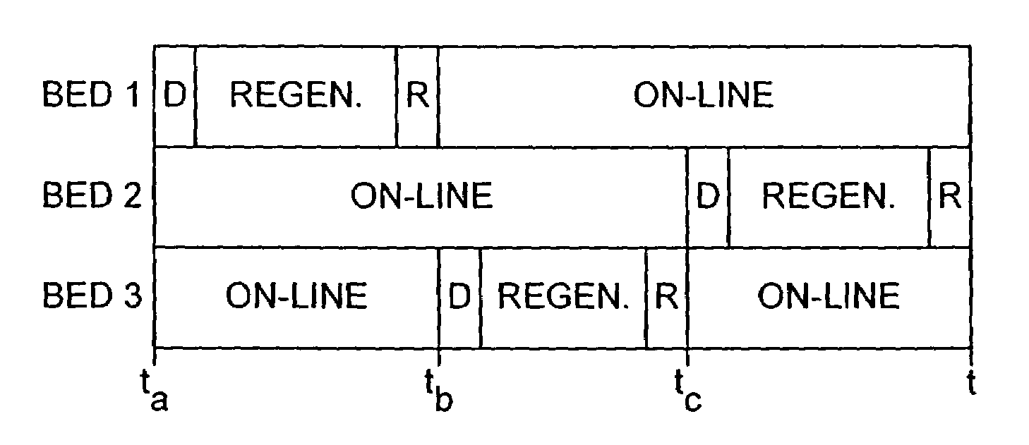
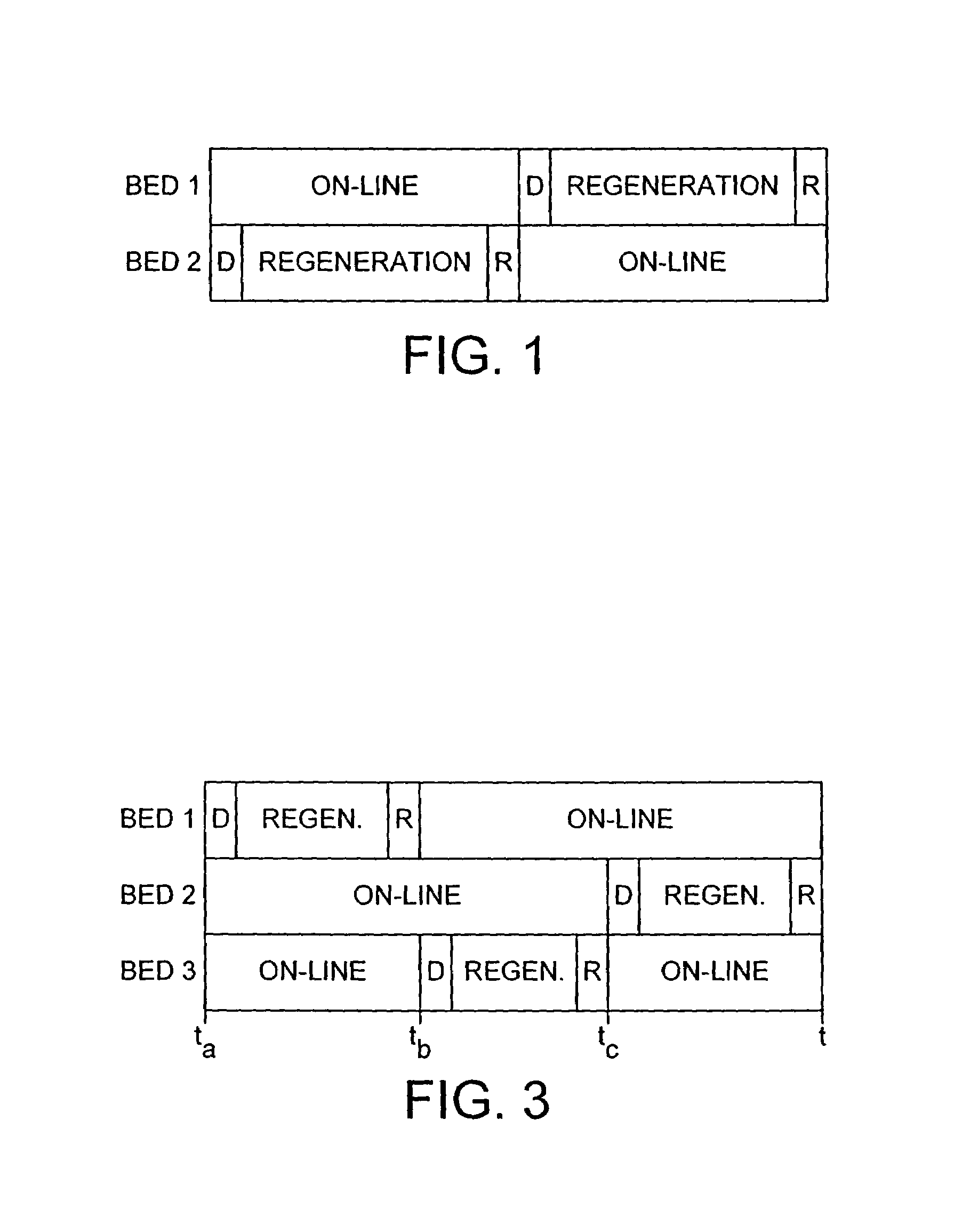
[0019]We have now found that technical problems such as undesirable fluid flow, bed fluidisation and unacceptable pressure drop and economic and practical problems including cost, design complexity and difficulties in transporting large-scale apparatus may be reduced or avoided by operating a TSA process using at least three adsorption zones in which, in use, at least two of the zones are always on-line and in which the feed gas is fed to the process continuously at a pressure which is generally constant in the adsorpt
Problems solved by technology
If relatively high boiling materials are not removed, they may liquefy or solidify in subsequent processing and lead to pressure drops, flow difficulties or other disadvantage in the downstream process.
Hydrocarbon gases, for example acetylene, may present such a hazard.
Depressurisation involves releasing pressurised gas and leads to waste, generally known as “switch loss”.
PSA therefore has certain disadvantages including unacceptable switch loss due to the relatively high frequency of switching between on-line operation and regeneration, especially in operating large capacity plant.
TSA, TPSA and TEPSA systems require the input of thermal energy and may require the use of insulated vessels, a regeneration gas preheater and an inlet end precooler and generally the high temperatures impose a more stringent and costly mechanical specification for the system.
In operation, there is extra energy cost associated with using the preheater.
Conventional purification in a TSA process, especially where larger vessels are employed, may be problematic because the flow characteristics of the gas being processed may place limitations due to the need to avoid undue fluidization of the adsorbent bed and unacceptable pressure drop.
In addition complex design of vessel geometry to address these issues, especiall
Method used
View moreImage
Smart ImageViewing Examples
Examples
 PUM
| Property | Measurement | Unit |
|---|---|---|
| Temperature | aaaaa | aaaaa |
| Temperature | aaaaa | aaaaa |
| Temperature | aaaaa | aaaaa |
Abstract
A process and an apparatus related to the reduction of the level of a component in a feed gas such as air involving passing the gas to at least three parallel thermal swing adsorption zones charged with an adsorbent and operating according to an adsorption cycle, wherein the cycle of each zone is phased with respect to that of the other zones so that at any point during the cycle, the number of zones in the adsorption step is greater than the number of zones not in the adsorption step.
Description
BACKGROUND OF THE INVENTION[0001]This invention relates to a process and apparatus for treating a feed gas. In particular, the invention relates to a thermal swing adsorption (TSA) process using at least three adsorption beds for removing or at least reducing the level of a component in a feed gas to render it suitable for downstream processing and apparatus for use in the process. The invention is especially useful in removing components from a feed gas on a large scale where conventional processes and apparatus are not suitable for use.[0002]Where a feed gas is to be subjected to downstream processing, it may often be desirable or necessary to remove certain components from the feed gas prior to such processing. As an example, high boiling materials for example water and carbon dioxide which may be present in a feed gas, for example air, must be removed where the mixture is to be subsequently treated in a low temperature, for example cryogenic, process. If relatively high boiling ...
Claims
Login to View More Application Information
Patent Timeline
 IPC IPC(8): B01D53/047B01D53/04F25J3/04F25J3/08
CPCB01D53/0462B01D53/0431Y02C10/08B01D53/261B01D2253/104B01D2253/106B01D2253/1085B01D2253/25B01D2253/304B01D2256/245B01D2257/504B01D2257/80B01D2259/40007B01D2259/40062B01D2259/40081B01D2259/4009B01D2259/402B01D2259/403B01D2259/404B01D2259/416Y02C20/40
Inventor KALBASSI, MOHAMMAD ALIHIGGINBOTHAM, PAUL
Owner AIR PROD & CHEM INC
Features
- R&D
- Intellectual Property
- Life Sciences
- Materials
- Tech Scout
- Unparalleled Data Quality
- Higher Quality Content
- 60% Fewer Hallucinations
Learn More Browse by: Latest US Patents, China's latest patents, Technical Efficacy Thesaurus, Application Domain, Technology Topic, Popular Technical Reports.
© 2025 PatSnap. All rights reserved.Legal|Privacy policy|Modern Slavery Act Transparency Statement|Sitemap|About US| Contact US: help@patsnap.com


