Wheel-like wire holder

a technology of wire holder and wheel, which is applied in the direction of machine supports, insulating bodies, television systems, etc., can solve the problems of troublesome binding work, inability to guarantee that the isolating central space is inaccessible to any surrounding wire, and inability to guarantee the inaccessibility of any surrounding wir

Inactive Publication Date: 2006-03-28
ORION ELECTRIC CO LTD
View PDF14 Cites 10 Cited by
  • Summary
  • Abstract
  • Description
  • Claims
  • Application Information

AI Technical Summary

Problems solved by technology

Disadvantageously, however, this wire holder structure permits another lead wire to invade through the loophole 4 and come close to the high-voltage wire 2.
Still disadvantageously, the wire holder can easily slide along the high-voltage lead wire 2, and thus, it cannot guarantee that an isolating central space is inaccessible to any surrounding wire.
This binding work, however, is troublesome, and the unbinding is troublesome, too.
Use of binding wires increases cost.

Method used


Image

  • Wheel-like wire holder
  • Wheel-like wire holder
  • Wheel-like wire holder

Examples


Embodiment Construction

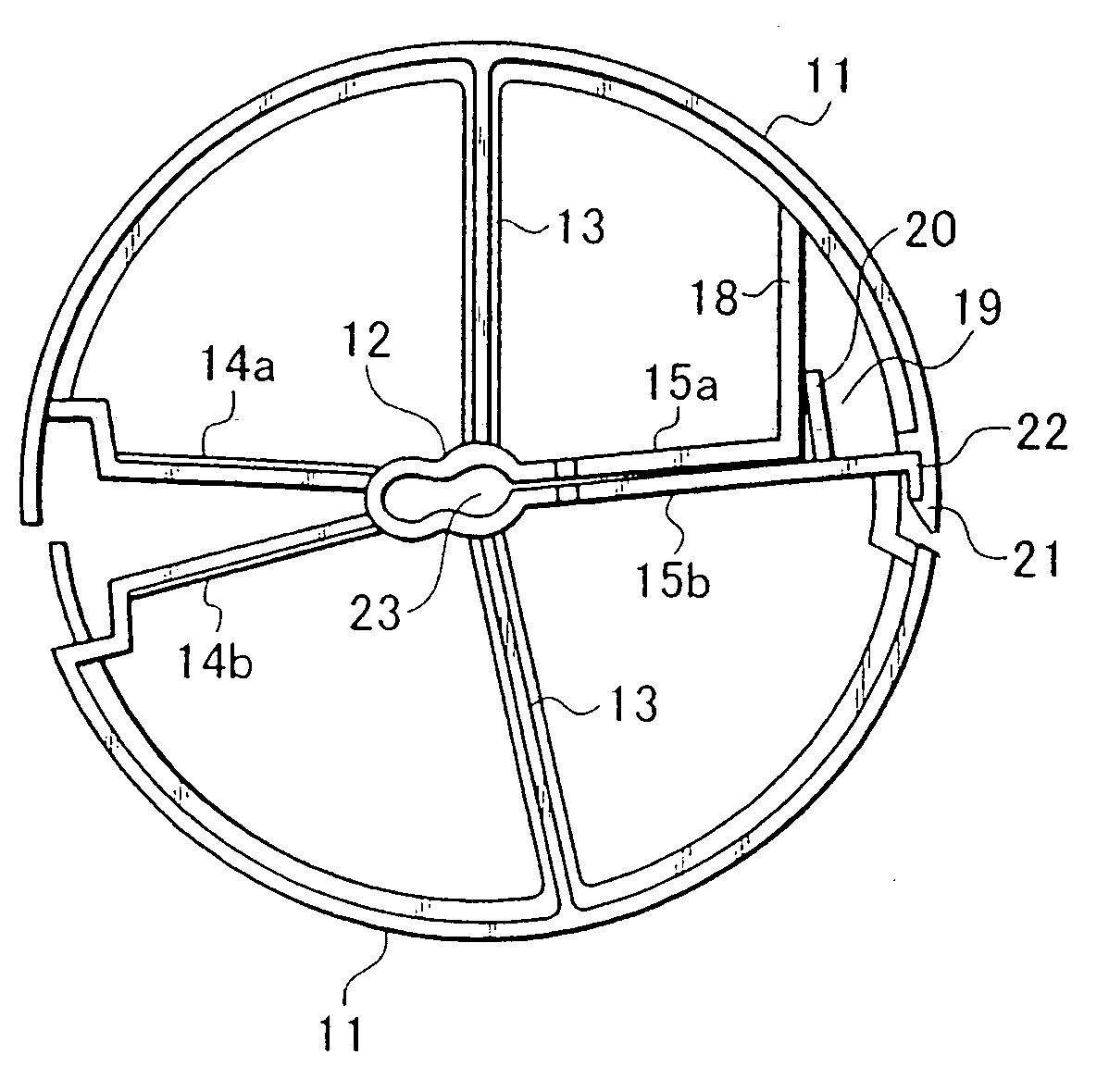
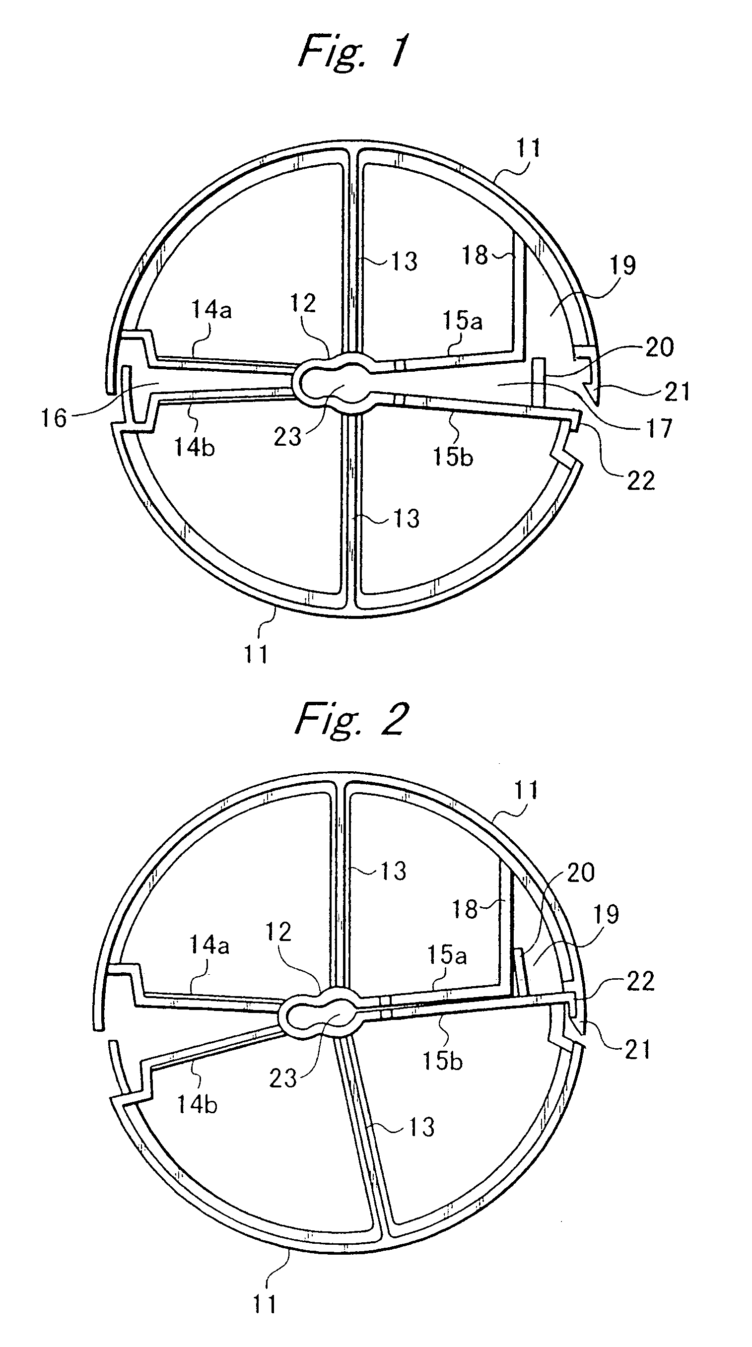
[0017]Referring to FIG. 1, a wheel-like wire holder according to one embodiment of the present invention comprises a ring 11, a central hub 12, and a plurality of spokes 13,13; 14a, 14b and 15a and 15b. These spokes connect the central hub 12 to the ring 11. The spokes 14a and 14b somewhat diverge outwardly to define a sector space 16 therebetween. Likewise, the spokes 15a and 15b somewhat diverge outwardly to define a sector space 17 therebetween. As seen from the drawing, these sector spaces 16 and 17 extend radially from central hub space 23 to the ring 11. The central hub space 23 and the sector space 17 form a loophole defined by opposite ends of the two spokes 15a, 15b radially extended toward the ring. The ring 11 is cut at two points between the spokes 14a and 14b, as well as between the spokes 15a and 15b, respectively, so that the sector spaces 16 and 17 are communicated with an exterior of the ring.

[0018]The central hub space 23 communicates with the sector space 17, and ...


PUM

PropertyMeasurementUnit
voltageaaaaaaaaaa
electromotive forceaaaaaaaaaa
equi-angular distanceaaaaaaaaaa

Abstract

To firmly hold a high-voltage wire apart from its surroundings, and hold some nearby lead wires apart from the high-voltage wire, a wheel-like wire holder includes a ring, a central hub, and a plurality of spokes connecting the central hub to the ring. The central hub defines a central space to allow a high-voltage lead wire to fit therein, wherein the ring and hub have cuts on their circumferences, which cuts are connected by two spokes to define a radial passage for the central space to communicate with an exterior of the ring. The cut of the ring is adapted to be open and closed, and the ring has an extra space defined next to the cut for accommodating another lead wire thereinside, with the extra space being adapted to be open and closed.

Description

BACKGROUND OF THE INVENTION[0001]1. Field of the Invention[0002]The present invention relates to a wheel-like wire holder for holding a live high-voltage wire at an isolating central space, which is inaccessible to any surrounding wire or parts.[0003]2. Related Art[0004]In a certain electric appliance such as a television receiver, a plurality of electric wires are used to apply electromotive force of high-frequency and / or high-voltage to some selected parts, and then such live wires need to be isolated from surrounding electric wires and parts so that no adverse effects or interference may be caused thereon. To assure that such live high-voltage or high-frequency wires are kept apart from the surrounding wires and parts, a variety of wire holders are used. One example of such a wire holder is shown in JP 5-85082(U), titled “Electric Wire Holder”.[0005]This wire holder looks like a wheel, comprising a ring, a central hub, two bifurcate spokes and one split-spoke connecting the centr...

Claims


Application Information

Patent Timeline
Patent Type & Authority Patents(United States)
IPC IPC(8): H01B17/00H02G3/30H02G3/32H05K7/00H04N5/64
CPCH02G3/32
Inventor SONO, YOSHIYUKI
Owner ORION ELECTRIC CO LTD
Why Eureka
Try Eureka