
Spray gun

Inactive Publication Date: 2006-03-28
SATA GMBH & CO KG
View PDF6 Cites 67 Cited by
  • Summary
  • Abstract
  • Description
  • Claims
  • Application Information

AI Technical Summary

Benefits of technology

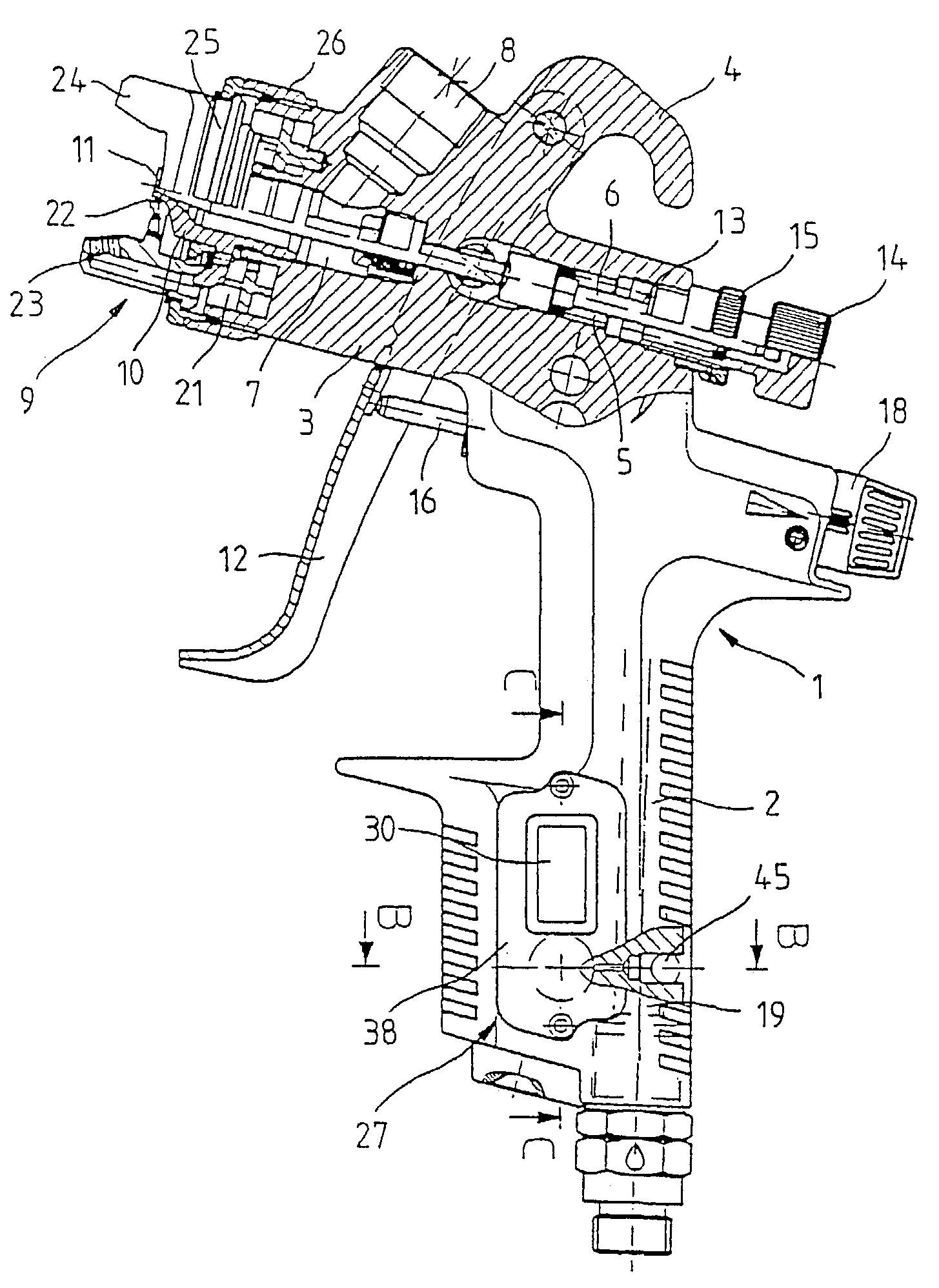
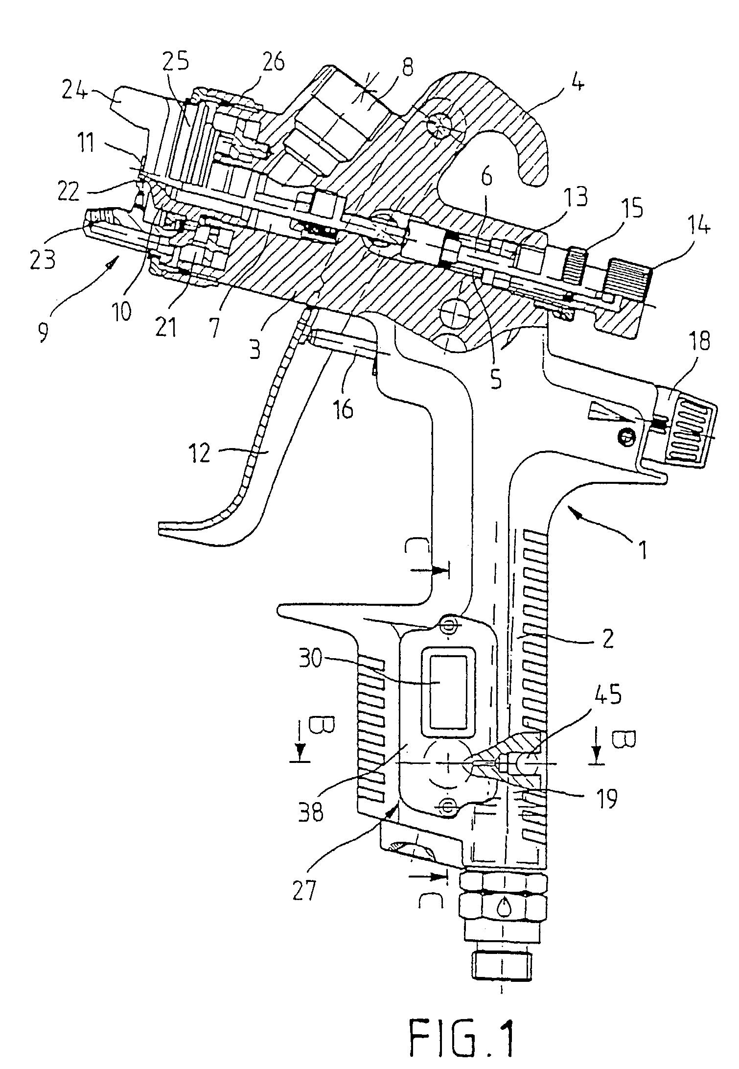
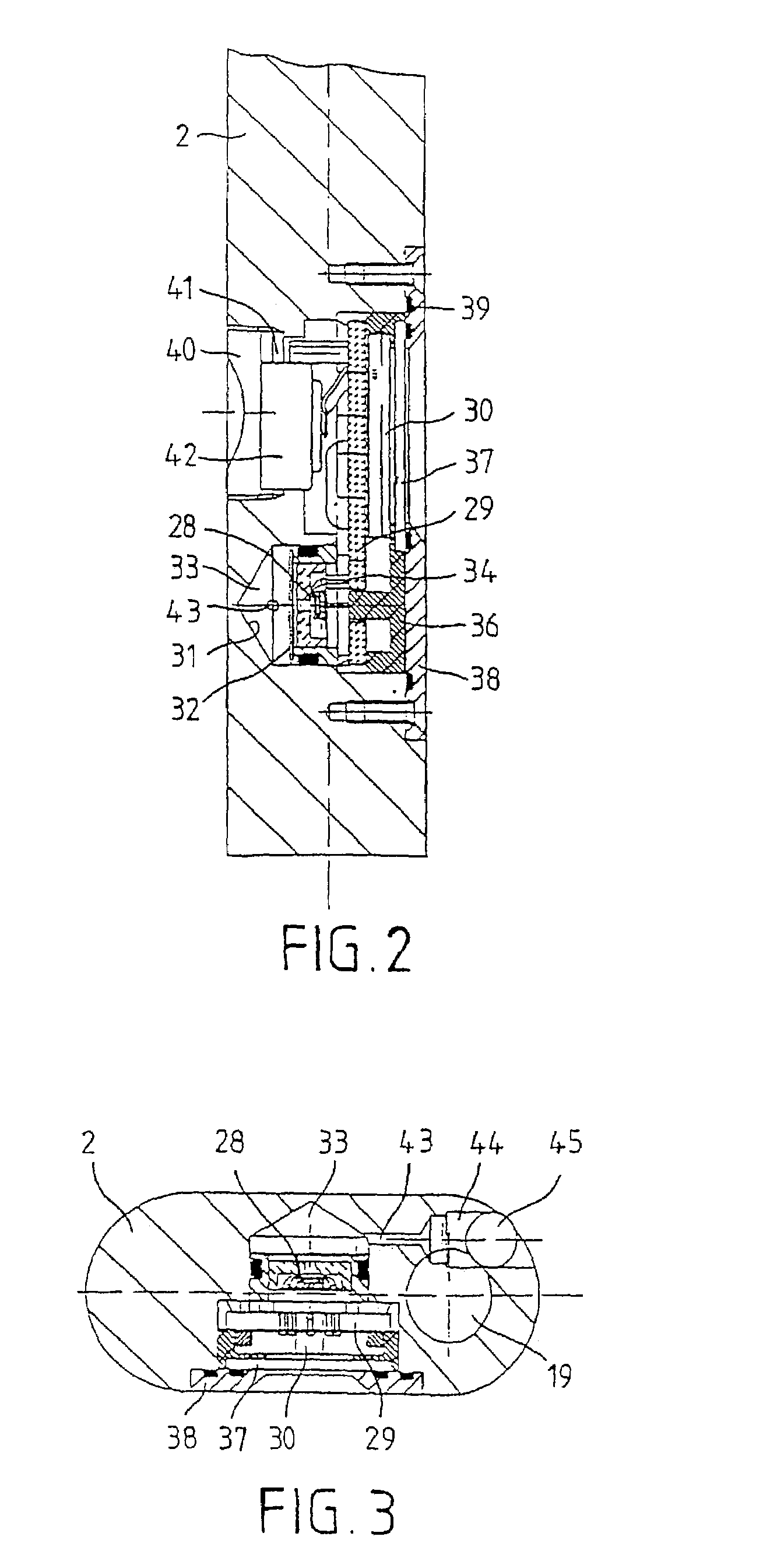
[0010]For the spray gun according to the invention, a pressure sensor of an integrated pressure-measurement device is also integrated in the gun body. This allows a very compact construction with a protected arrangement of the pressure sensor in the interior of the paint spray gun. In addition, the pressure sensor is connected to a compressed-air supply channel by means of a capillary tube. This capillary tube can prevent solvent used for cleaning the spray gun and coating or paint residue from penetrating into the region of the pressure sensor, which could negatively affect or prevent a regular pressure measurement. The paint spray gun according to the invention can be cleaned without disassembly of the measurement device, and there is no risk to the usually sensitive pressure sensor.
[0012]In an especially preferred embodiment, the display device and an optional circuit arrangement for signal conversion and evaluation is also integrated, e.g., in the handle of the spray gun. In this way, the entire measurement device is mounted within the gun body and is optimally protected there against damage.
[0013]However, the display device, which can be configured as an analog or digital display, can be arranged on a rear end portion of the gun body such that the display field can be read from behind. This produces the advantage that the pressure display is always in the field of view during spraying.
[0014]In one possible embodiment, the capillary tube can be arranged in a connection channel, which lies between a pressure detection compartment and the air supply channel in the region of the gun inlet upstream of a valve assembly. In this configuration, the gun inlet pressure can be detected. However, the capillary tube can also be arranged in a connection channel between the pressure detection compartment and a part downstream of the valve device. In this way, the air pressure, which is adjusted by means of a regulator at the valve assembly and which is used for spraying, can be detected and displayed.

Problems solved by technology

A spraying pressure that is too low can lead, e.g., to color changes in the base coating, to an increase in the orange-peel structure in clear coatings and plain lacquer, and to a reduction of working speed and possibly the stream width.
On the other hand, a spraying pressure that is too high can cause too great an atomization of the spray material and thus to greater losses and undesired stress on the work environment.
However, this pressure-regulating valve with manometer at the air inlet of the paint spray gun leads to a lengthening of the spray gun, which produces poorer handling.
In addition, due to the rerouted inner channels, the manometer or the pressure-regulating valve produces a pressure drop.
Also, the pressure-regulating valve, which is usually screwed on, must be disassembled for cleaning the spray gun in washing devices or cleaning tanks, because the display accuracy of the manometer can be negatively affected by solvent or coating or paint residue entering the instrument.
Therefore, the pressure-regulating valve with the manometer must be removed for each cleaning process, which is associated with considerable work effort.
However, for this configuration, the handling of the spray gun is also negatively affected by the coupled manometer.
In addition, the manometer must be removed for cleaning the paint spray gun, so that relatively expensive coupling or connecting systems are required for connecting the manometer to the spray gun.
Such a spray gun also exhibits worse handling due to the manometer, which projects outward to one side.

Method used


Image

  • Spray gun
  • Spray gun
  • Spray gun

Examples


Embodiment Construction

[0027]The spray gun illustrated in FIG. 1 includes a gun body 1 with a handle 2 and a top part 3, on which a hanger hook 4 is formed. A through-hole 5, which extends from front to back, which has several stages, and in which a nozzle pin 6 can move in the axial direction, runs through the top part 3. The through-hole 5 forms an expanded receptacle 7 at the front, where there is an inclined supply hole 8 for mounting a paint storage container (not shown). A nozzle assembly 9 is attached to the front end of the through-hole 5. This nozzle assembly includes a paint nozzle 10 that can be fixed by means of threads on the top part 3 of the gun body 1. At its front end, the paint nozzle 10 has a nozzle hole 11, which provides a controllable supply of paint, coating, or the like, together with a front end part of the nozzle pin 6 that can move in the axial direction by means of a control lever 12 and that feeds the tip of the gun. The control lever 12 is connected to the nozzle pin 6 such t...


PUM


Abstract

A spray gun having a gun body; a nozzle assembly arranged on the gun body; a compressed air supply channel located in the gun body, controlled by a valve assembly, a regulator for adjusting the supply of the spray material, an actuating element for actuating the valve assembly) and the regulator and a pressure measuring device. A pressure measuring device, resistant to dirt, that contains a pressure sensor integrated into the gun body and is connected to the compressed air supply channel via a capillary (43) located within the gun body.

Description

BACKGROUND OF THE INVENTION[0001]1. Field of the Invention[0002]The invention relates to a spray gun.[0003]2. Prior Art[0004]When working with a spray gun, it is extremely important to adjust the spraying pressure to produce optimum atomization for optimum work results at a good working speed and high application efficiency. A spraying pressure that is too low can lead, e.g., to color changes in the base coating, to an increase in the orange-peel structure in clear coatings and plain lacquer, and to a reduction of working speed and possibly the stream width. On the other hand, a spraying pressure that is too high can cause too great an atomization of the spray material and thus to greater losses and undesired stress on the work environment. Also, during the spraying process, the available pressure should be monitored to recognize possible pressure drops due to additional loads on the compressed-air network or pressure increases due to the activation of resources.[0005]Frequently a p...

Claims


Application Information

Patent Timeline
IPC IPC(8): B05B7/02B05B12/00B05B12/08
CPCB05B12/008Y10S239/14B05B7/2478
Inventor SCHMON, EWALD
Owner SATA GMBH & CO KG
Learn More