Calender

a calender and calender technology, applied in the field of calenders, can solve the problems of increasing the danger of accidents and fires, affecting the existence of paper factories, and affecting the safety of workers, and achieve the effect of increasing safety

Inactive Publication Date: 2006-03-21
VOITH PATENT GMBH
View PDF17 Cites 0 Cited by
  • Summary
  • Abstract
  • Description
  • Claims
  • Application Information

AI Technical Summary

Problems solved by technology

In this regard, in the event of machine damage in the area of the connection arrangement, there is an increased danger of accidents and fire, e.g., due to splashing oil that can ignite and then burn or due to components flying about, e.g., when a rotary transmission is damaged.
Such damage can cause considerable secondary damage in the area around the calender, e.g., to the paper machine, to the switchboard galleries, to the crane or even to people who are in the hall in which the calender is also located.
Under certain circumstances they can even jeopardize the existence of the paper factory if other important machines, e.g., the paper machine, break down in addition to the calender.

Method used


Image

  • Calender
  • Calender
  • Calender

Examples


Embodiment Construction

[0041]The particulars shown herein are by way of example and for purposes of illustrative discussion of the embodiments of the present invention only and are presented in the cause of providing what is believed to be the most useful and readily understood description of the principles and conceptual aspects of the present invention. In this regard, no attempt is made to show structural details of the present invention in more detail than is necessary for the fundamental understanding of the present invention, the description taken with the drawings making apparent to those skilled in the art how the several forms of the present invention may be embodied in practice.

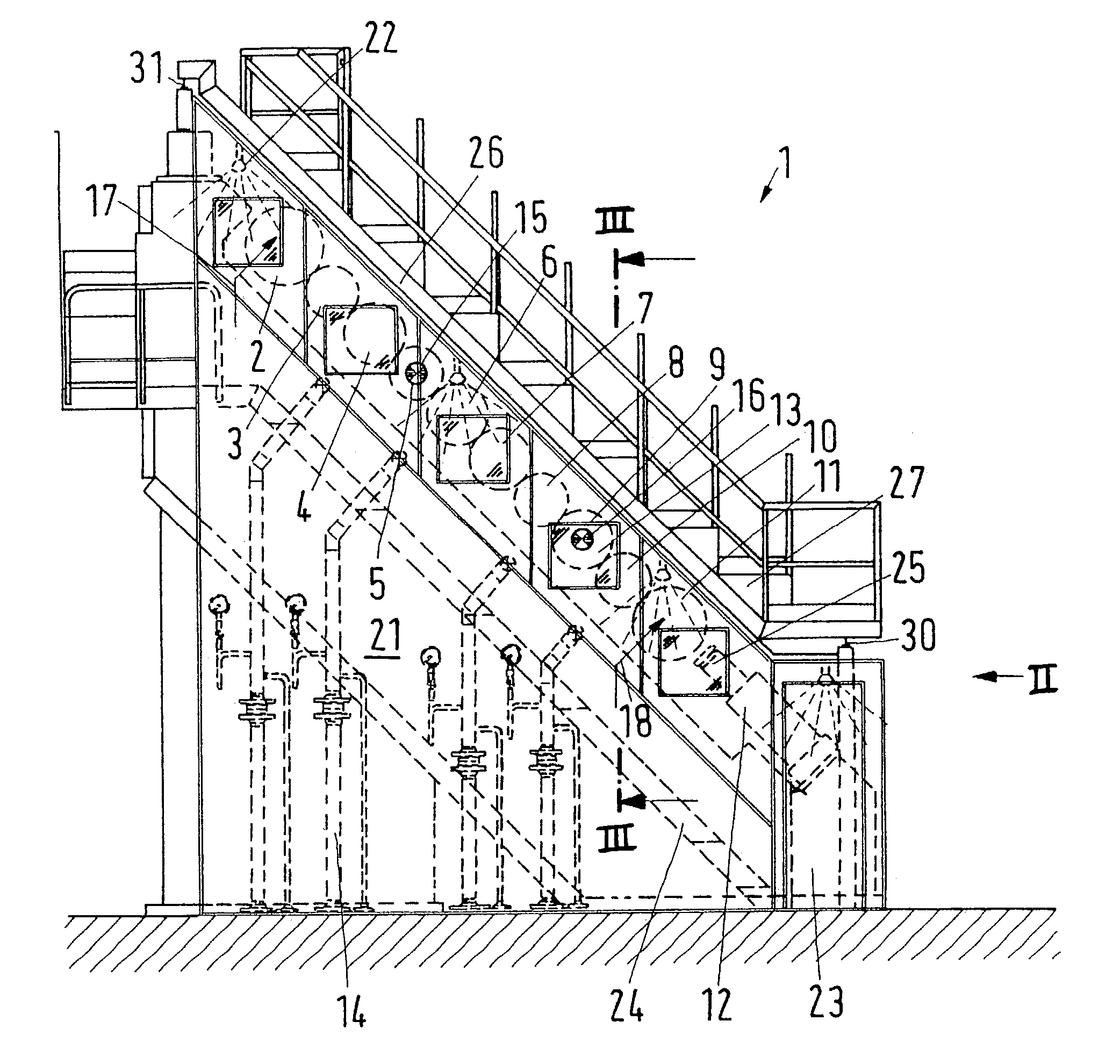
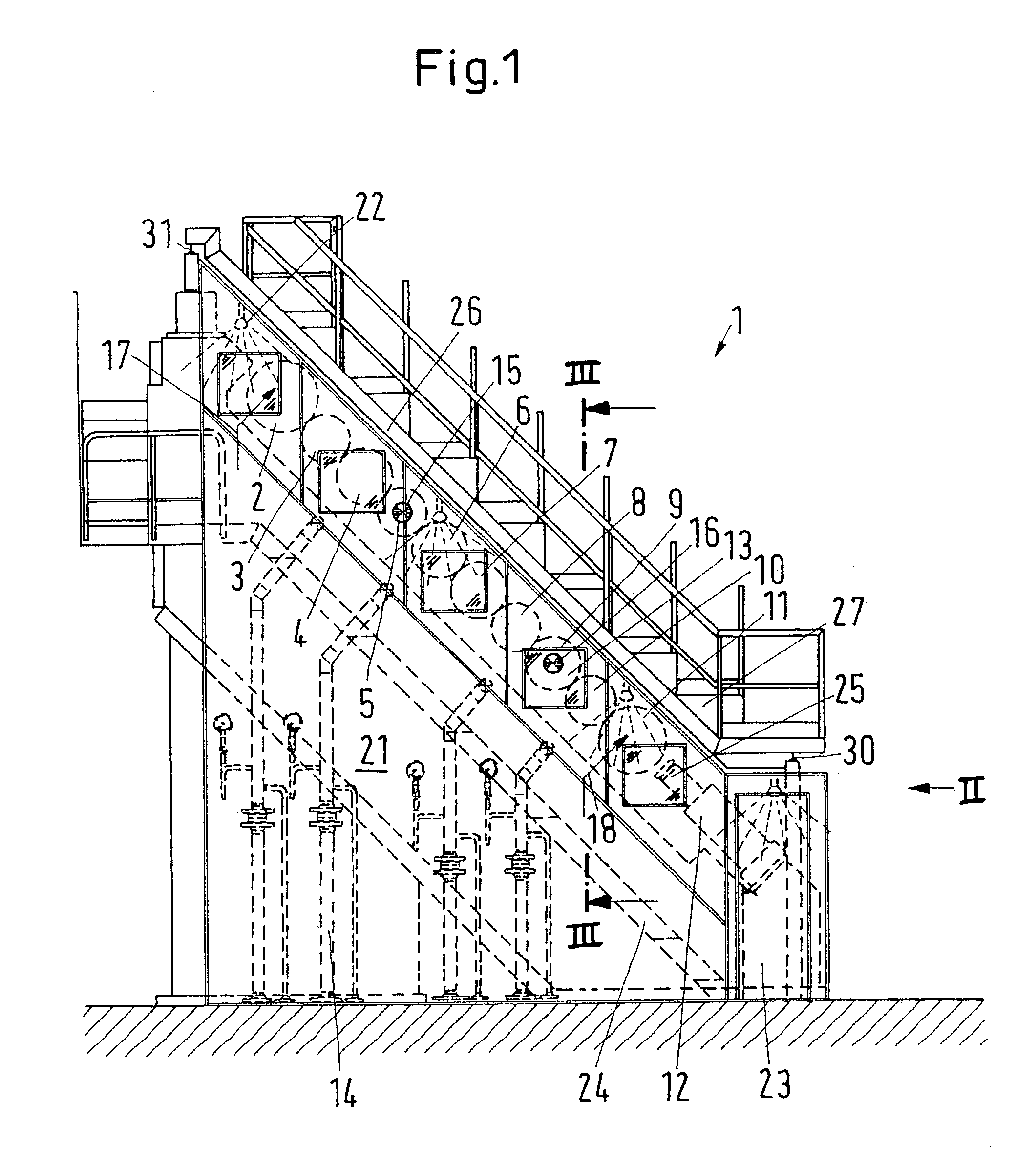
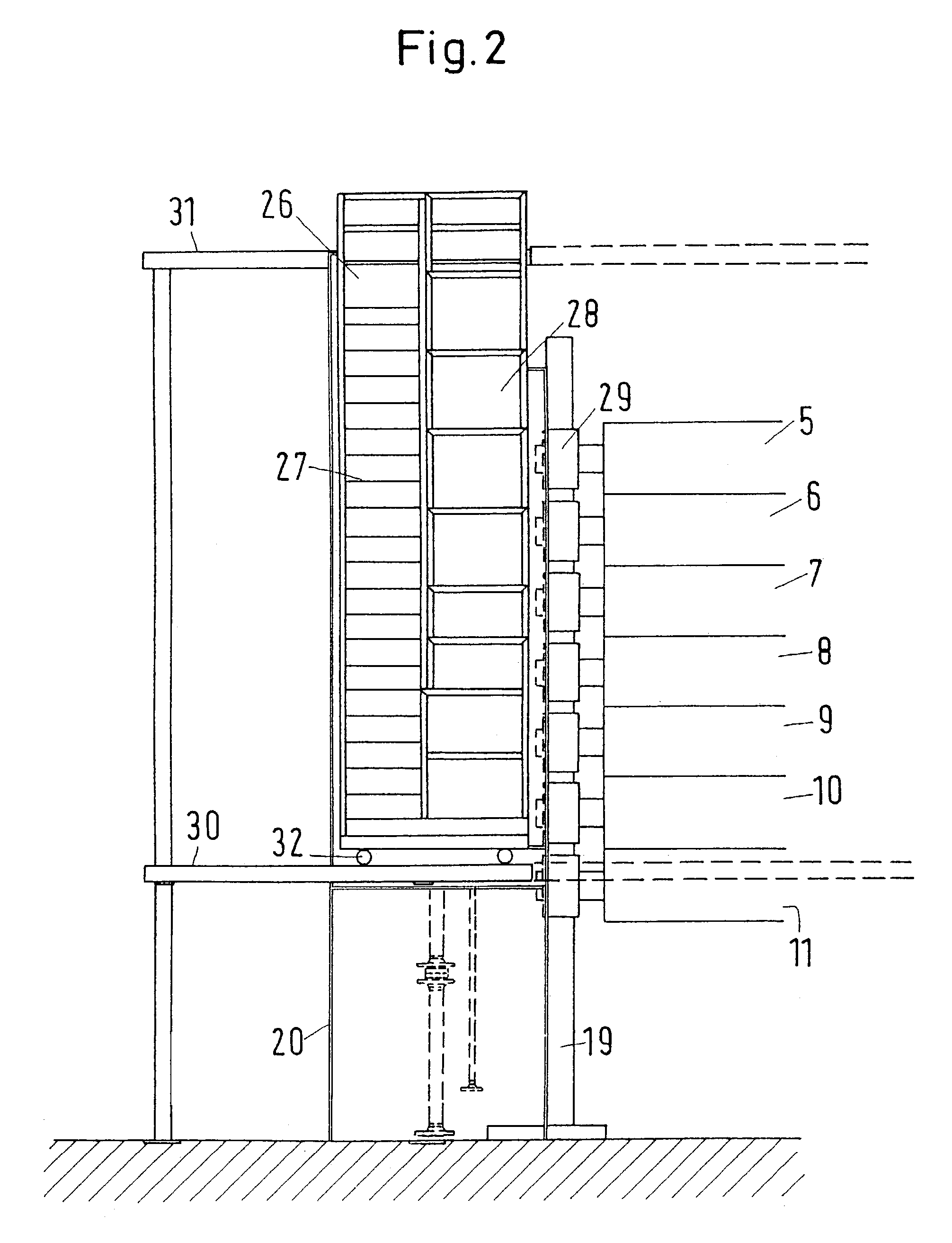
[0042]A calender 1 according to FIGS. 1–5 features a roll stack with a plurality of rolls, e.g., rolls 2–11. In FIG. 2, upper three rolls 2–4 are dismantled for ease of illustration. The roll stack is tilted at an angle of about 45° to the horizontal. In a manner known per se, top end roll 2 and bottom end roll 11 are emb...


PUM


Abstract

Calender that includes at least one supporting bracket, and a roll stack having at least two rolls. At least one axial end of each of the at least two rolls are supported by the at least one supporting bracket. A connection arrangement includes a fluid connection coupled to at least one of the at least two rolls and a drive connection coupled to at least one of the at least two rolls, and a closed housing is arranged to enclose the connection arrangement. The instant abstract is neither intended to define the invention disclosed in this specification nor intended to limit the scope of the invention in any way.

Description

CROSS-REFERENCE TO RELATED APPLICATIONS[0001]The present application claims priority under 35 U.S.C. §119 of German Patent Application No. 102 01 349.7, filed on Jan. 16, 2002, the disclosure of which is expressly incorporated by reference herein in its entirety.BACKGROUND OF THE INVENTION[0002]1. Field of the Invention[0003]The present invention relates to a calender with a roll stack of at least two rolls that are supported in brackets in the area of their axial ends and with a connection arrangement such that at least one roll has a fluid connection and at least one roll has a drive connection.[0004]2. Discussion of Background Information[0005]Such a calender is used to glaze a material web, e.g., a paper web. To this end the material web is guided through at least one nip that is formed by two neighboring rolls that are pressed against one another. With a roll stack featuring more than two rolls, there is a correspondingly higher number of nips in which the material web can be a...

Claims


Application Information

Patent Timeline
Patent Type & Authority Patents(United States)
IPC IPC(8): B30B3/04D21G1/00D21G5/00
CPCD21G1/00D21G5/005D21G1/0073
Inventor HENDRIX, GOTTFRIED
Owner VOITH PATENT GMBH
Why Eureka
Try Eureka