
Histogram adjustment features for use in imaging technologies

Active Publication Date: 2006-02-28
8324450 DELAWARE +1
View PDF15 Cites 99 Cited by
  • Summary
  • Abstract
  • Description
  • Claims
  • Application Information

AI Technical Summary

Benefits of technology

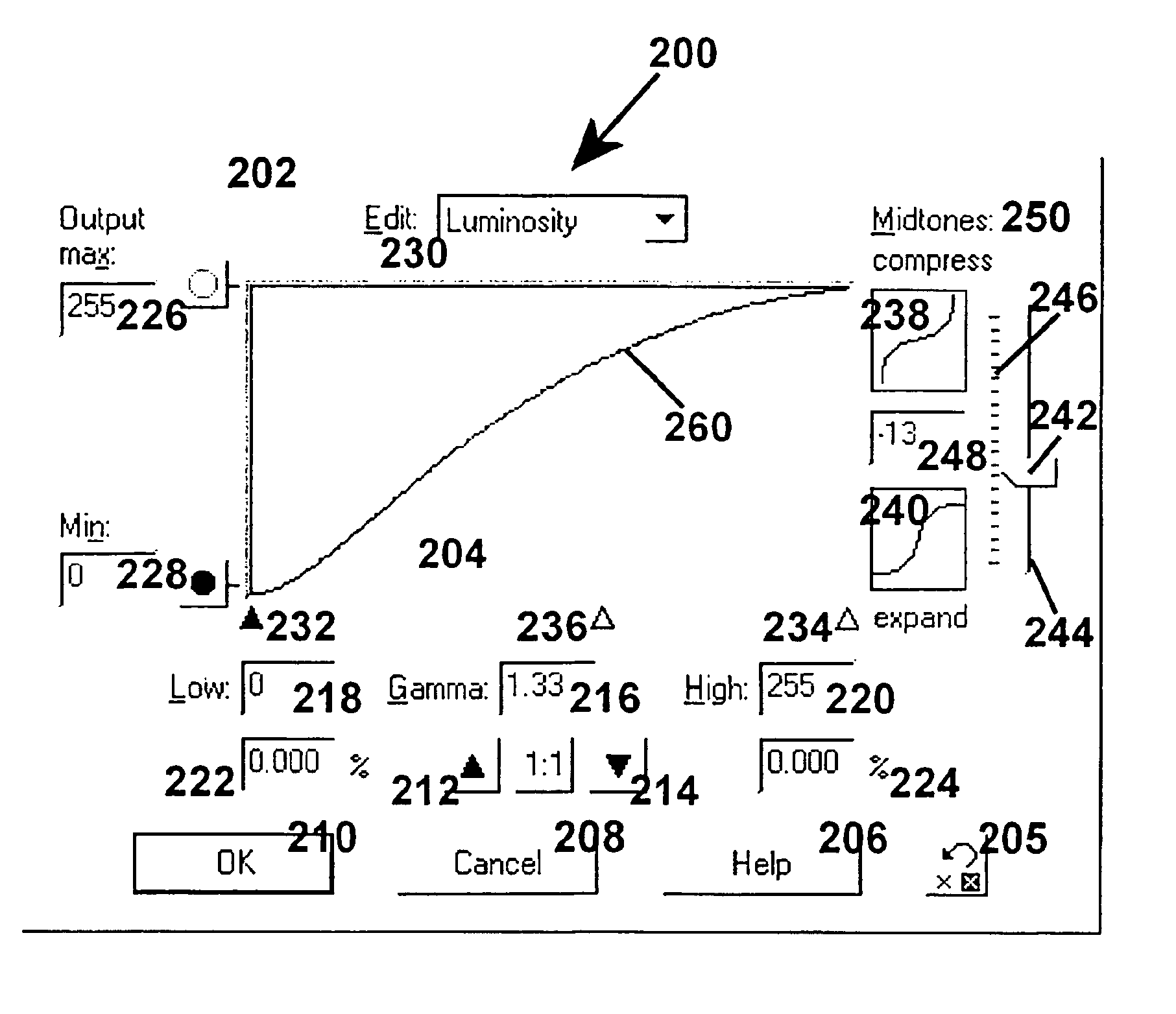
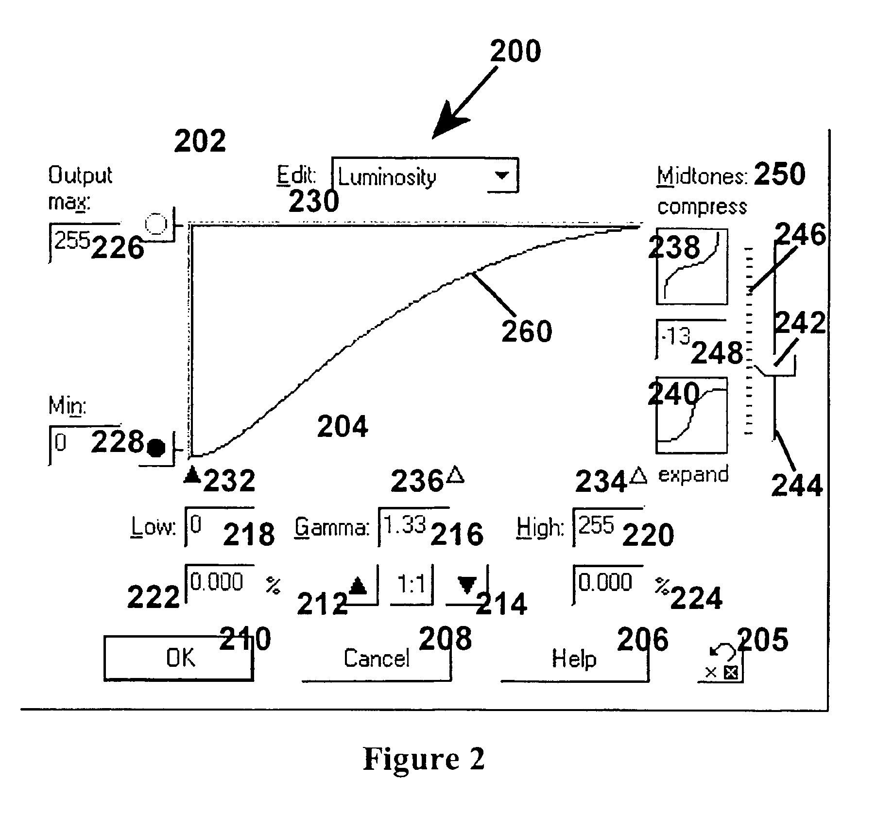
[0024]A viewable program is provided by software that displays a histogram of image data, a screen image viewed on a monitor displays the histogram, an analog (e.g., slider) or digital (e.g., numerical, spin control or step function click spots) control element that controls compression and expansion of midtones and wherein activation of the midtone compression/expansion element accordingly alters the displayed histogram according to effects of programs underlying the movement of the element, this h

Problems solved by technology

For example, the scanner can impact the quality if the scanner is not properly calibrated.
Also, the output (printing) device can impact the quality if a printhead is clogged or a photoreceptor is not properly cleaned.
Excessively dark images have histograms with large peaks in regions of low intensity and excessively bright images have large peaks in regions of high intensity.
The correction of image data on a PC or networked computer can be complex

Method used


Image

  • Histogram adjustment features for use in imaging technologies
  • Histogram adjustment features for use in imaging technologies
  • Histogram adjustment features for use in imaging technologies

Examples


examples

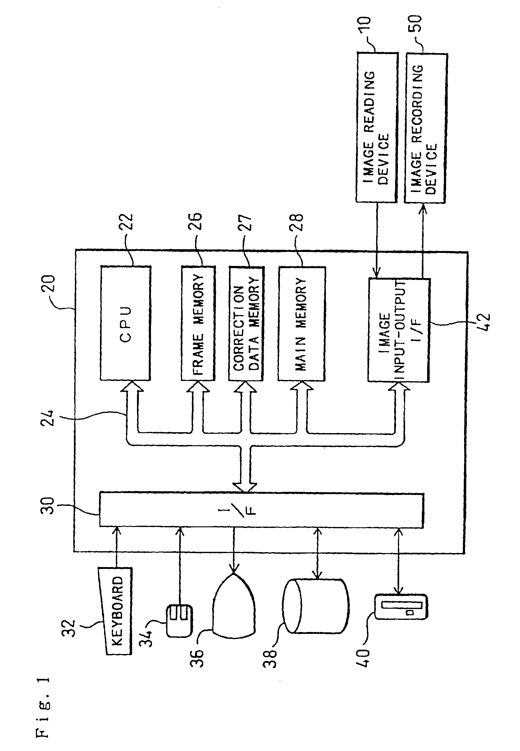
[0077]FIG. 1 is a block diagram illustrating structure of an image processing system with an apparatus for determining image processing parameters incorporated therein as one embodiment according to the present invention. The image processing system includes an image reading device 10, an image processing apparatus 20, and an image recording device 50. The image reading device 10 is realized, for example, by an input scanner or a digital camera that reads image data of a color image. The image reading device 10 outputs image data (R, G, and B signals) DR, DG, and DB of the respective color components obtained by scanning an image of an original by every pixel. The image reading device 10 may otherwise be realized by a magnetic disk in which image data are stored or a compact disk (CD) or in the form of a network communicated with another device via a communications line.

[0078]The image processing apparatus 20 is realized by a computer system, such as a work station or a personal com...


PUM


Abstract

A computer with a monitor viewable program executes to display a histogram of image data on the monitor. The monitor contemporaneously displays a screen image viewed on a monitor of the histogram, and displays a digital or analog control element that controls both compression and expansion of midtones. Activation of the midtone compression/expansion element alters the displayed image according to effects of programs underlying the control of the element. This histogram display and element are associated on a single logical screen display in which at least one other image data modification effect is present on the screen image as an addressable image data modification effect.

Description

BACKGROUND OF THE INVENTION[0001]1. Field of the Invention[0002]The present invention relates to the field of imaging technology, correction or adjustment of images and image data, the adjustment of image properties, and the use of look-up-tables and sliders on view screens to systematically adjust the visual properties of images and image data.[0003]2. Background of the Art[0004]Images and image data can be represented in many different terms and in many different scientific formats, and many different types of properties can be used to assist in defining the image and the components of the image. A basic point or component in defining an image is known in the art as a pixel, the pixel being the smallest unit of information used to construct or define an image or the properties of an image. A pixel, depending upon the method in which the image is rendered, may vary in absolute size or proportions to the image, and the pixel itself may be composed of smaller units that need not be d...

Claims


Application Information

Patent Timeline
IPC IPC(8): G06K9/00G06T5/40
CPCG06T5/40G06T5/009
Inventor ZAKLIKA, KRYZSTOF ANTONITRIFONOV, MIKHAIL IVANOVICHSHARONOVA, OLGA VADIMOVNA
Owner 8324450 DELAWARE
Learn More