
Method and apparatus for air-to-air aircraft ranging

a technology for air-to-air aircraft and ranging, which is applied in the direction of navigation instruments, instruments for comonautical navigation, instruments, etc., can solve the problems of large range estimation error, large range determination error, and to-air passive ranging, so as to reduce the error measurement, minimize the error measurement, and eliminate the disadvantages and problems.

Inactive Publication Date: 2006-02-21
RAYTHEON CO
View PDF16 Cites 32 Cited by
  • Summary
  • Abstract
  • Description
  • Claims
  • Application Information

AI Technical Summary

Benefits of technology

[0007]In accordance with the present invention, a air-to-air passive ranging apparatus is provided which substantially eliminates or prevents the disadvantages and problems associated with prior art passive ranging systems.
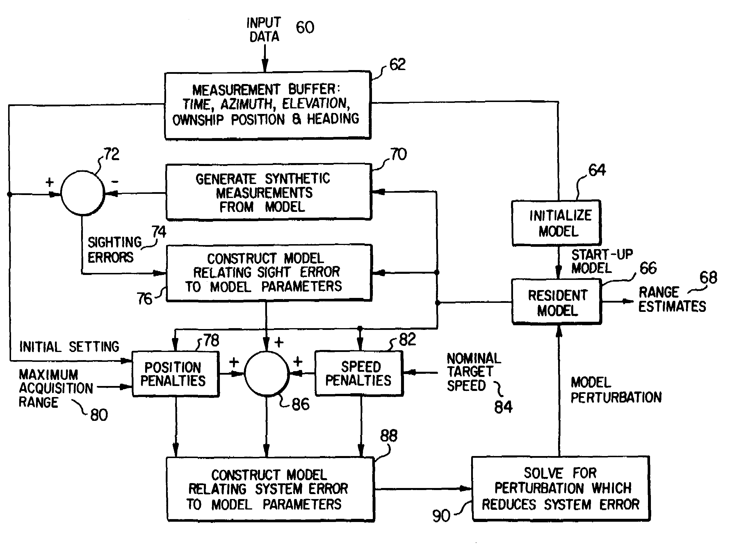
[0009]In yet another aspect of the invention, the error measurement comprises a means squared sighting error, a velocity related error, and three position related errors. A system error is defined as the sum of the means squared sighting error, the velocity error and the three position errors. A perturbation model is determined such that the sum of the model data and the perturbation model data will result in a new set of model data which reduces the error measurement.

Problems solved by technology

The dominant problem in air-to-air passive ranging is ill-conditioning.
Ill-conditioning refers to small errors in the directional measurements causing much larger errors in the range estimate.
The sources of ill-conditioning include the limited baseline over which data is measured and the need to infer target motion from the data.
Since sightings projected from a short baseline are nearly parallel, a small error in the measured angle results in a large error in determination of range.
However, the desire to determine range as quickly as possible restricts the baseline that may be developed during data collection.
However, this is not true of the air-to-air problem, where target motion must be considered.
This aggravates ill-conditioning because it diminishes the redundancy by which information may be distinguished from noise in the data.
Unresolved noise in the data produces ranging errors.

Method used


Image

  • Method and apparatus for air-to-air aircraft ranging
  • Method and apparatus for air-to-air aircraft ranging
  • Method and apparatus for air-to-air aircraft ranging

Examples


Embodiment Construction

[0022]The preferred embodiment of the present invention is best understood by referring to FIGS. 1–10 of the drawings, like numerals being used for like and corresponding parts of the various drawings.

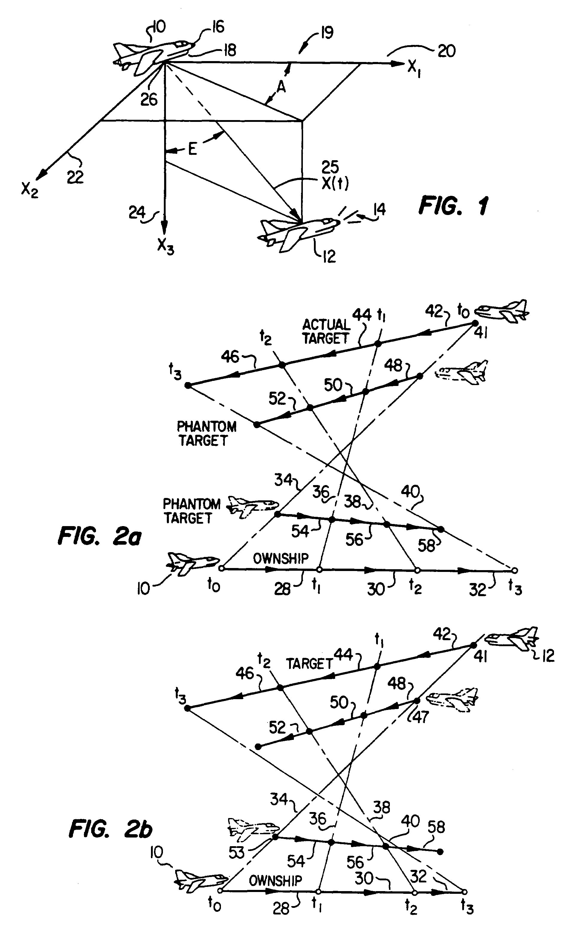
[0023]FIG. 1 illustrates an aerial encounter between two aircraft. Ownship 10 desires to determine the range between itself and a second aircraft, target 12. Target 12 emits electromagnetic energy, generally indicated by the reference numeral 14. Ownship 10 contains directional receivers 16 operable to determine the angle-of-arrival of the incoming energy forces 14 at various times during a data collection and interval. In addition to the bearing measurements, fixes of ownship's position and heading are monitored by the on-board inertial navigation system (INS) 18. A rectangular coordinate system 19 having an X1 axis 20, an X2 axis 22, and an X3 axis 24, has its center 26 located at ownship. The coordinate system 19 moves in pure translation with ownship 10; however, the directions of ...


PUM


Abstract

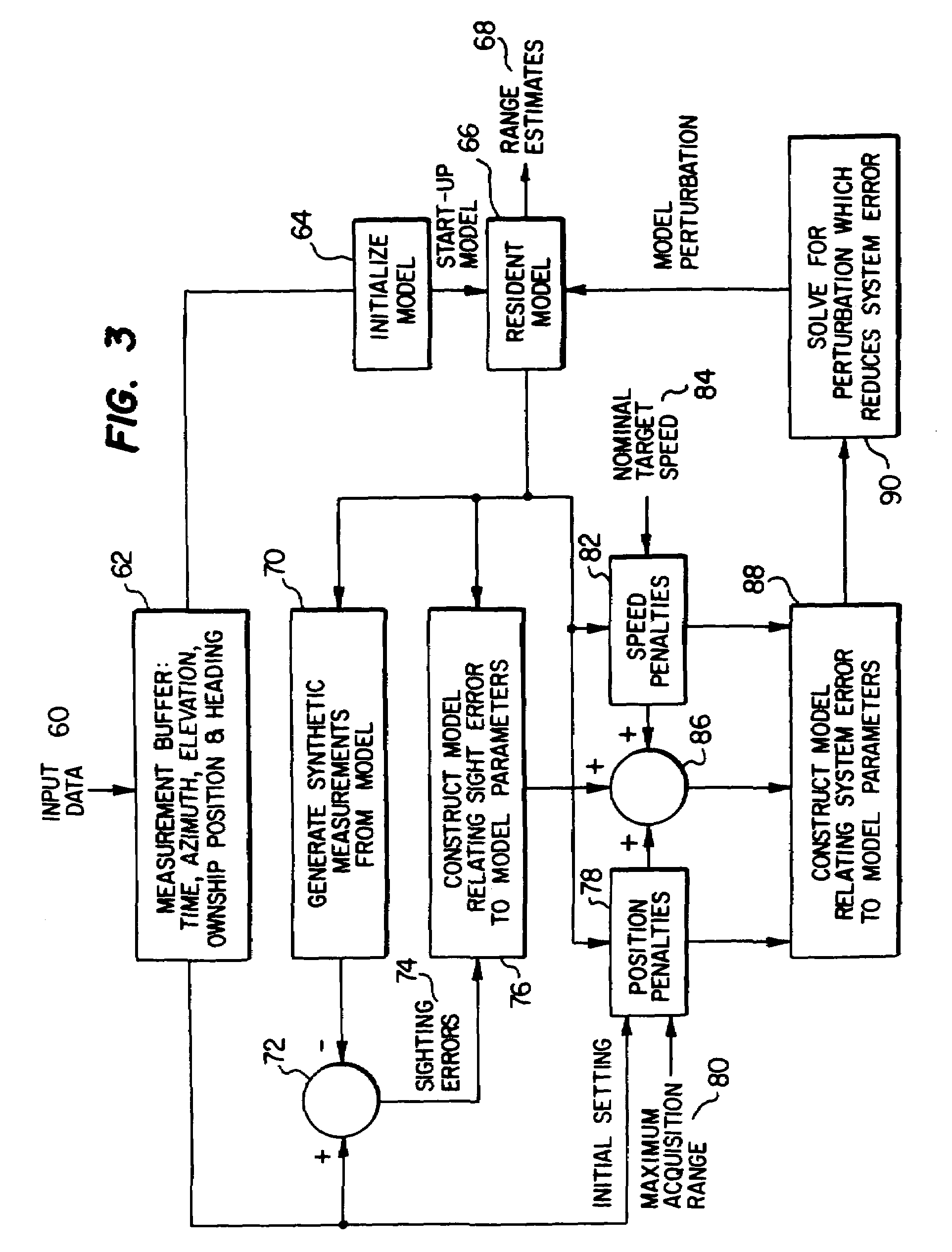
A method and apparatus is disclosed for determining the range between two planes, ownship (10) and target (12). Model data (66) estimating the velocity and position of target (12) is compared to actual flight path data of the target (12) passively received by ownship (10). The model data (66) and actual data is compared, and an error measurement is calculated. The model data is also subject to position and velocity constraints (78 and 82) which penalize unrealistic estimates. The error measurement and penalties are used to create a perturbation model (90) which is added to the model data to generate new model data. When the model data (66) conforms closely to the actual data, a range is computed from the model data (66).

Description

[0001]This application is a Continuation of application Ser. No. 07 / 008,432, filed Jan. 28, 1987 now abandoned.TECHNICAL FIELD OF THE INVENTION[0002]This invention relates in general to methods and apparatus for determining the range from one aircraft to another aircraft, and more particularly relates to methods and apparatus for determining the range through use of passive energy detection with directional receivers.BACKGROUND OF THE INVENTION[0003]The goal of air-to-air passive ranging is to determine the range (distance) from one aircraft, called “ownship”, to another, called “target”, by means of electromagnetic energy emanating from target. For this purpose, ownship is equipped with directional receivers operable to determine the angle of arrival of the incoming energy at various times during a data collection interval. In most applications, the energy detected will be in the radio frequency (RF) or infrared (IR) portions of the spectrum. By combining the directional measuremen...

Claims


Application Information

Patent Timeline
Patent Type & Authority Patents(United States)
IPC IPC(8): G01S13/08
CPCG01S11/04
Inventor CHOATE, WILLIAM CLAYFREY, CHARLES EMILJUNGMANN, JAMES ANTHONY
Owner RAYTHEON CO
Learn More