
Wire winding device for receiving network wires or telephone wires

a wire winding device and telephone wire technology, applied in the direction of current collectors, flexible lead accommodation, coupling device connections, etc., can solve the problems of inconvenient wire carrying, difficult to arrange prior art design in order, inconvenient to carry a wire, etc., to achieve convenient carrying and beautiful outlook

Inactive Publication Date: 2006-02-21
CHIANG WU SUNG
View PDF6 Cites 30 Cited by
  • Summary
  • Abstract
  • Description
  • Claims
  • Application Information

AI Technical Summary

Benefits of technology

[0003]The present invention has been accomplished to provide a wire winding device for receiving network wires or telephone wires, wherein the wire in the device can be connected to a computer or a telephone and furthermore, the electric wire can be received within a wall or a desk so as to have a beautiful outlook. Thereby since the wall is wound in the cover, it can be carried conveniently. Thereby the electric wire of the present invention can be used in various devices.

Problems solved by technology

However this prior art design is difficult to be arranged in order.
Thereby it is inconvenient to carry a wire.
The wire is difficult to be arranged in order for storage.
Thereby these inconvenient makes the wire easily damaged.
Furthermore, the prior art wire is generally used for computer devices, but it cannot be used for telephones.

Method used


Image

  • Wire winding device for receiving network wires or telephone wires
  • Wire winding device for receiving network wires or telephone wires
  • Wire winding device for receiving network wires or telephone wires

Examples


Embodiment Construction

[0012]In order that those skilled in the art can further understand the present invention, a description will be described in the following in details. However, these descriptions and the appended drawings are only used to cause those skilled in the art to understand the objects, features, and characteristics of the present invention, but not to be used to confine the scope and spirit of the present invention defined in the appended claims.

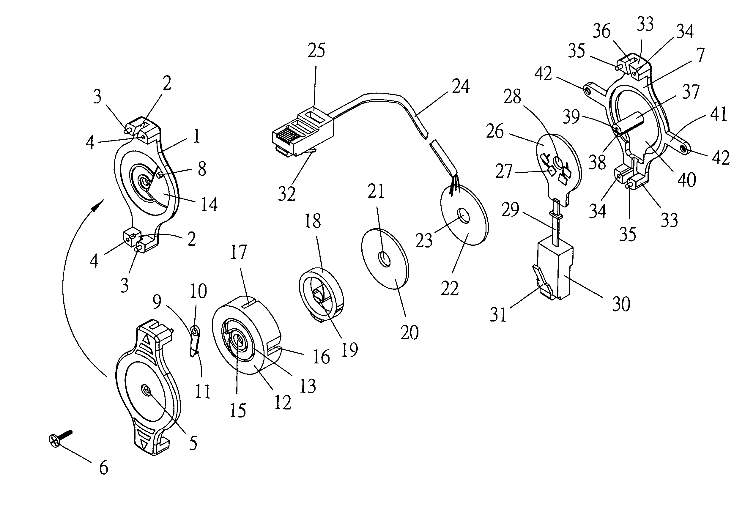
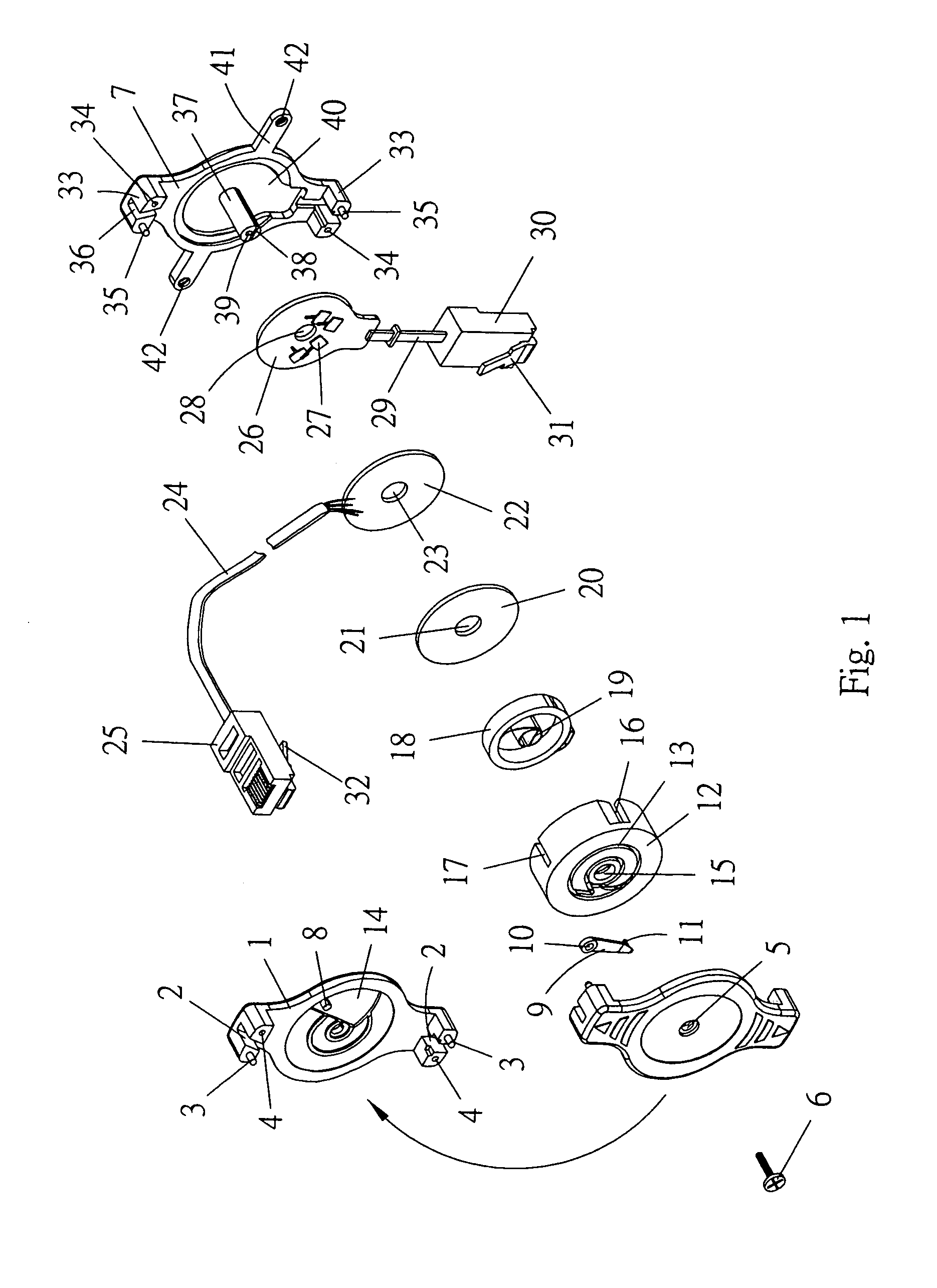
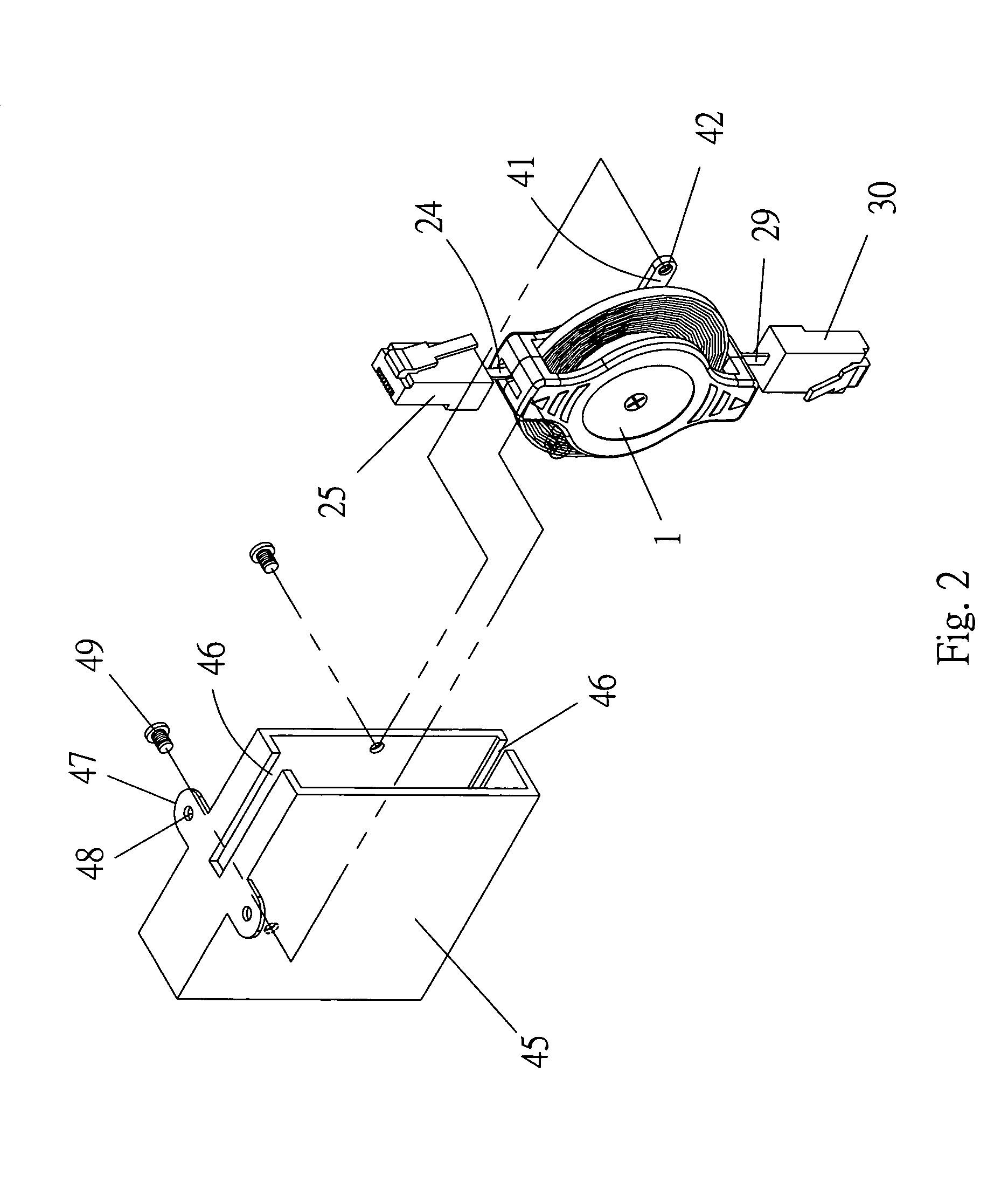
[0013]With reference to FIGS. 1, 2, 3, 4 and 5, the present invention is illustrated. The present invention is related to a wire winding device which can be hidden in a wall. The device has a multi-functional joint which can be pulled out to be connected to a computer or a telephone. The device comprises the following elements.

[0014]An upper cover 1 has two ends. Each end has two protrusion posts. The two protrusion posts are formed with a slot 2 therebetween. One of the two protrusion posts at the same end has a tenon 3 and the other has a groove...


PUM


Abstract

A wire winding device for receiving network wires or telephone wires is disclosed. The round post of the lower cover passes through the via hole of the circuit board, the central hole of the conducting plate, the via hole of the insulating plate; the buckling hole of the spring; the via hole of the spring seat, and the via hole of the upper cover, sequentially. The buckle sheet is engaged to the upper cover. The buckling post of the buckle sheet is movable fixed to the buckling groove. The upper cover and lower cover are combined. The electric wire of the circuit board and the electric wire of the conducting plate are placed in the slot of the upper cover and the slot of the lower cover. A screw serves to lock the upper cover to the lower cover.

Description

FIELD OF THE INVENTION[0001]The present invention relates to wire winding devices, and in particular to a wire winding device for receiving network wires or telephone wires, wherein the wire in the device can be connected to a computer or a telephone and furthermore, the electric wire can be received within a wall or a desk so as to have a beautiful outlook. Thereby since the wall is wound in the cover, it can be carried conveniently.BACKGROUND OF THE INVENTION[0002]Currently, a computer is connected to other devices by electric wires through the connections of plugs, such as USB plugs. Generally, in some usage, the wire is made as an extension wire which is an independent wire. The wire is portable. In use, one end of the wire is connected to a computer and another end of the wire is connected to an appliance device. However this prior art design is difficult to be arranged in order. Thereby it is inconvenient to carry a wire. The wire is difficult to be arranged in order for stora...

Claims


Application Information

Patent Timeline
IPC IPC(8): H01R13/72
CPCH01R13/72
Inventor CHIANG, WU SUNG
Owner CHIANG WU SUNG
Learn More