
Method of manufacturing outer races for tripod-type constant velocity universal joints

a technology of constant velocity universal joints and outer races, which is applied in the direction of engine components, mechanical equipment, couplings, etc., can solve the problems of inability to meet the requirements of production, so as to facilitate the upsetting step

Inactive Publication Date: 2006-02-21
NTN CORP
View PDF21 Cites 11 Cited by
  • Summary
  • Abstract
  • Description
  • Claims
  • Application Information

AI Technical Summary

Benefits of technology

This approach simplifies the punch and mold design, reduces manufacturing complexity, and facilitates precise finishing of chamfered portions through the plastic working process, improving productivity and ease of repair.

Problems solved by technology

While the chamfered portions are generally defined by the use of a cutting process, the use of the cutting process is undesirable in terms of productivity and yield of production.
However, since the chamfered portions are formed during the cup forming process, the punch used to form the cup portion is required to have a complicated shape wherein.
Since the punch for formation of the cup portion is one of elements of a mold used to define the track grooves and the reduced diameter portion between the neighboring track grooves, such punch has a relatively complicated shape.
Accordingly, if the tapered surface area referred to above is formed to render the punch to represent a stepped configuration, the punch is indeed complicated considerably in shape.
For this reason, the punch for formation of the cup portion will become difficult to manufacture and, more over, once such punch is worn down, repair thereof is difficult to achieve.
By way of example, if when the punch is worn down the punch is desired to be repaired by removing a worn end portion thereof, the tapered area must also be repaired, making it difficult to repair the punch.

Method used


Image

  • Method of manufacturing outer races for tripod-type constant velocity universal joints
  • Method of manufacturing outer races for tripod-type constant velocity universal joints
  • Method of manufacturing outer races for tripod-type constant velocity universal joints

Examples


Embodiment Construction

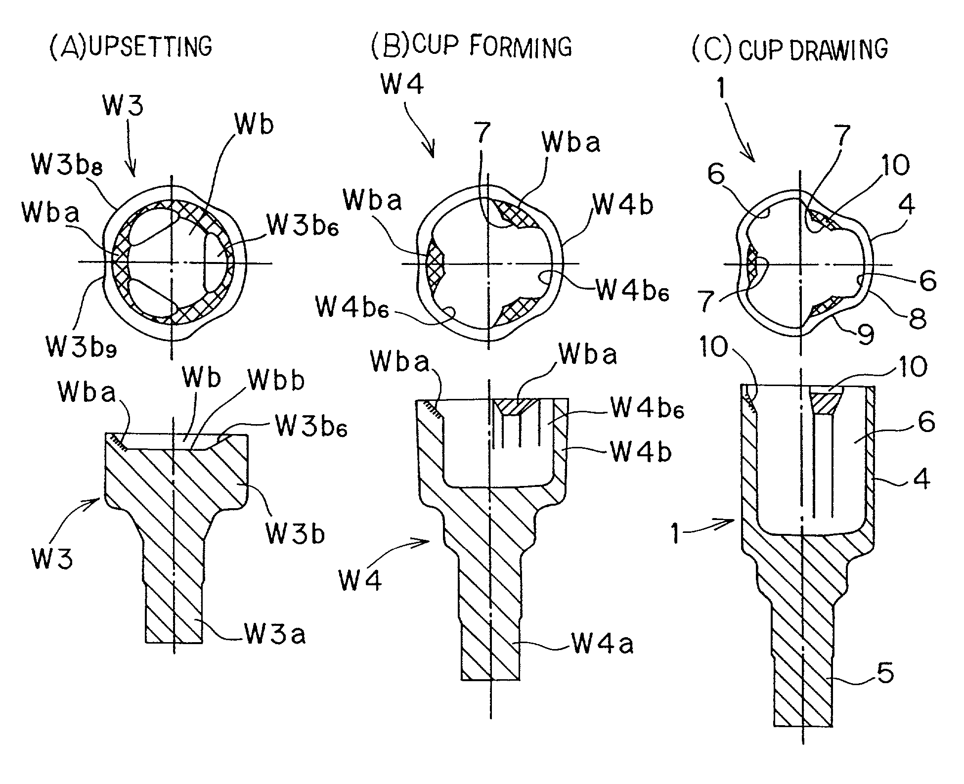
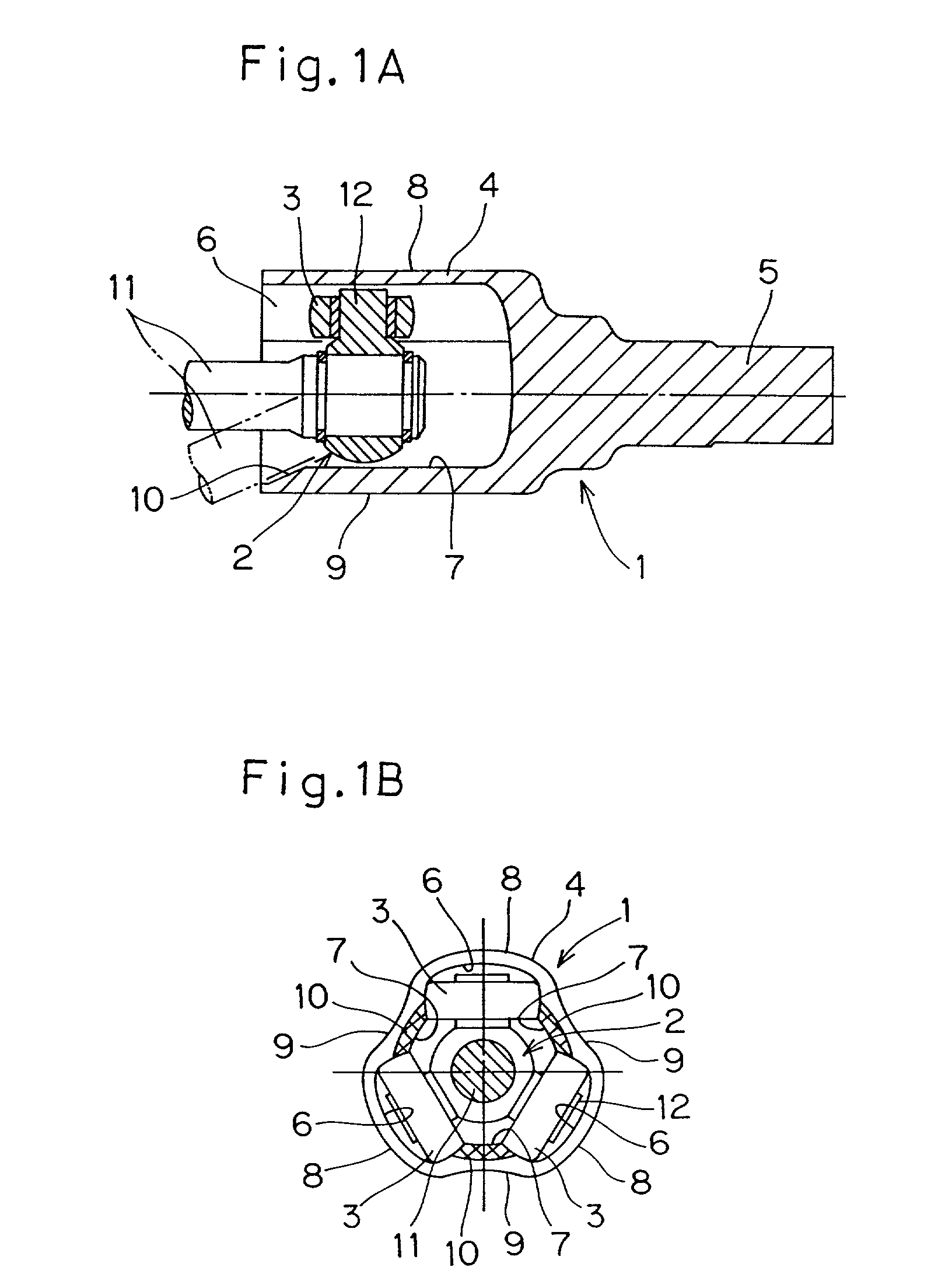
[0031]A preferred embodiment of the present invention will now be described. As shown in FIGS. 1A and 1B, a constant velocity universal joint of a tripod type employing an outer race manufactured in accordance with the present invention includes, in addition to the outer race 1, an inner race 2 and three rolling elements 3. The outer race 1 in turn includes a cup body 4 and a first shaft 5 extending outwardly from a bottom or closed end of the cup body 4 in coaxial relation therewith. The cup body 4 has its inner peripheral surface formed with three track grooves 6 defined therein so as to extend axially thereof and spaced an equal distance from each other in a direction substantially circumferentially thereof.

[0032]Notwithstanding the presence of the track grooves 6, the cup body 4 has a peripheral wall and the presence of the track grooves 6 in the inner peripheral surface of the cup body 4 leaves the peripheral wall of the cup body 4 to have a radially outwardly protruding wall p...


PUM

PropertyMeasurementUnit
diameteraaaaaaaaaa
shapeaaaaaaaaaa
dimensionaaaaaaaaaa

Abstract

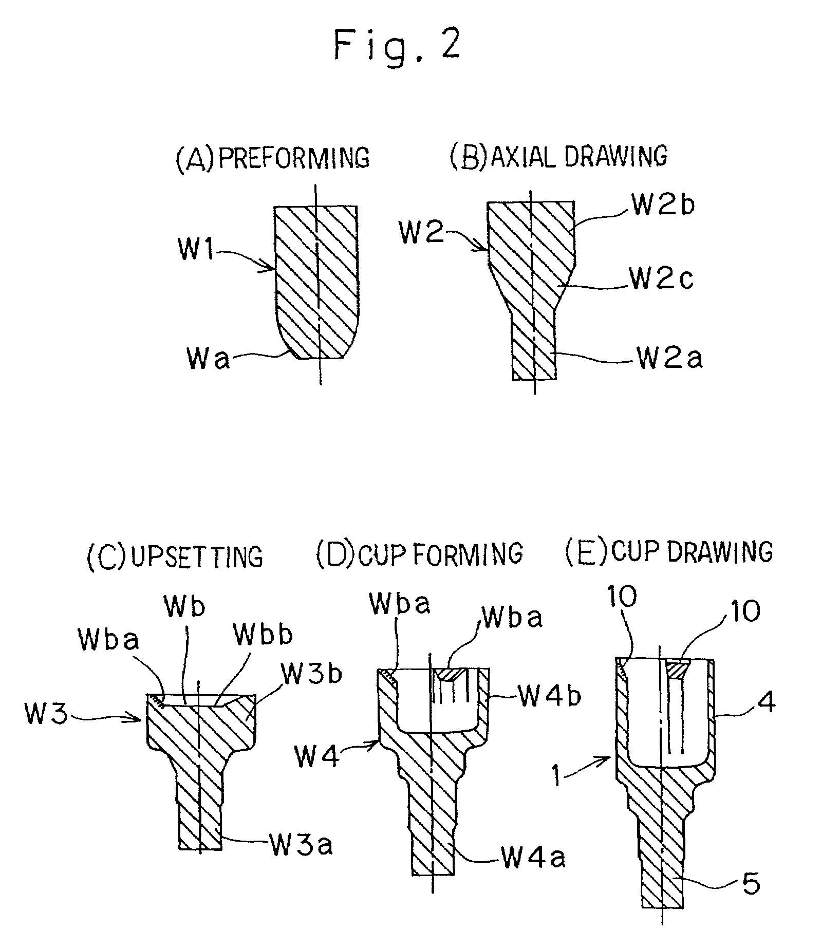
To make a peripheral lip region to be formed with chamfered portions by the use of a plastic working technique, to enable the use of a cup forming punch of a simplified shape so that a mold used therewith can be easily assembled and the punch when worn down can easily be repaired, a method of making an outer race of a constant velocity universal joint of a tripod type includes an upsetting step during which not only are outer peripheral shapes of a small diameter portion (W3a) and a large diameter portion (W3b) defined, but a recess (Wb) having a tapered peripheral wall face (Wba), which eventually defines general shapes of the chamfered portions (10) of the outer race (1), is formed in an end face of the large diameter portion (W3b). During a cup forming step, the tapered peripheral wall face (Wba) defined during the upsetting step is rearwardly pushed while its shape is maintained. Thereafter, a cup drawing step is carried out to finish the tapered peripheral wall face (Wba) to represent the final design shapes of the chamfered portions (10).

Description

BACKGROUND OF THE INVENTION[0001]1. Field of the Invention[0002]The present invention relates to a method of manufacturing an outer race for a constant velocity universal joint of a tripod type, mainly for automotive use, by the utilization of a plastic working process and, more particularly, to the method of the kind referred to, wherein a chamfered area of a peripheral lip region of an opening is subjected to the plastic working process.[0003]2. Description of the Prior Art[0004]The constant velocity universal joint of the tripod type generally includes an outer race having a cup body formed with three track grooves, an inner race positioned inside the outer race, and rolling elements intervening between the outer and inner races in operative engagement with the associated track grooves. In this type of the constant velocity universal joint, assuming that the outer and inner races are rotating in unison with each other, a shaft coupled with the inner race can undergo a rocking mot...

Claims


Application Information

Patent Timeline
Patent Type & Authority Patents(United States)
IPC IPC(8): B21D53/10F16D3/20B21J5/08B21K1/14B21K1/76
CPCB21K1/762B21K1/765Y10T29/49657Y10T29/49648Y10T29/49689Y10T29/49636Y10T29/49647F16D3/2055
Inventor IIHARA, MICHIOSAGISAKA, YOSHIHIROSHINKAI, TAKESHI
Owner NTN CORP
Learn More