Ceiling fixture with easy installation features

a technology of installation features and ceiling fans, which is applied in the direction of lighting and heating apparatus, lighting support devices, coupling device connections, etc., can solve the problem that the installation of ceiling fans is a difficult task for a single installer

Inactive Publication Date: 2006-02-14
ANGELO FAN BRACE LICENSING
View PDF121 Cites 43 Cited by
  • Summary
  • Abstract
  • Description
  • Claims
  • Application Information

AI Technical Summary

Benefits of technology

[0004]The present invention provides an easily installed ceiling fan or other electrically-powered ceiling fixture. The fan includes a quick connect device for electrically and physically mounting the fan to a ceiling.
[0006]In a preferred embodiment, the plate is a receptacle plate that mounts onto an electrical junction box, and the first electrical contact is an electrical receptacle that can be connected to supply wires in the electrical junction box. The second electrical contact is an electrical plug of the type that mates with the receptacle, such as a three- or four-prong plug. The plug is rotatably mounted in the canopy and is connected to electrical conductors for supplying electricity to the electrically-powered components of the fixture, such as a fan motor, a light, and any fan accessories. The rim of the canopy is provided with L-shaped slots for a “bayonet” connection with studs or screws projecting from the rim of the plate. The quick connect device is so dimensioned that as the fan is raised, first the pins of the plug engage in their respective sockets in the receptacle. At this stage, the studs or screws on the plate need not be aligned with the L-shaped slots in the canopy. Then the rim of the canopy engages with the studs or screws on the plate. At this stage, the canopy can be rotated, while the pins of the plug remain engaged in the receptacle, so that the studs or screws can be brought into alignment with the mouths of the L-shaped slots. Then the fixture is raised further, the studs or screws enter the L-shaped slots, and the plug engages fully with the receptacle. The canopy is then rotated, so that the studs or screws enter the horizontal inner ends of the L-shaped slots. The studs or screws can then support the weight of the fixture, leaving the installer with both hands free to tighten those screws and / or insert other screws or fastenings to secure the canopy to the plate.

Problems solved by technology

The installation of a ceiling fan is a difficult task for a single installer.

Method used


Image

  • Ceiling fixture with easy installation features
  • Ceiling fixture with easy installation features
  • Ceiling fixture with easy installation features

Examples


Embodiment Construction

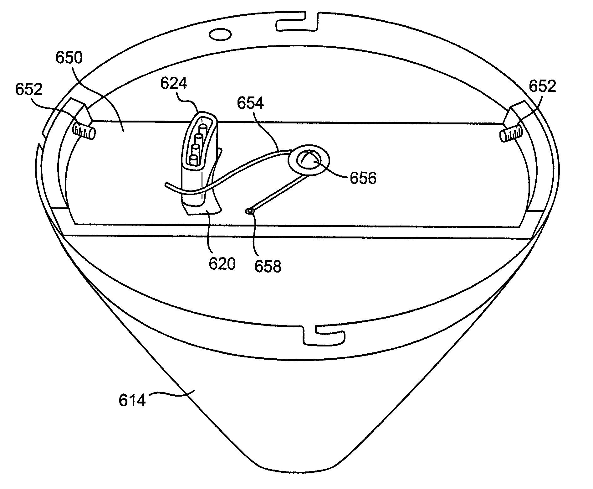
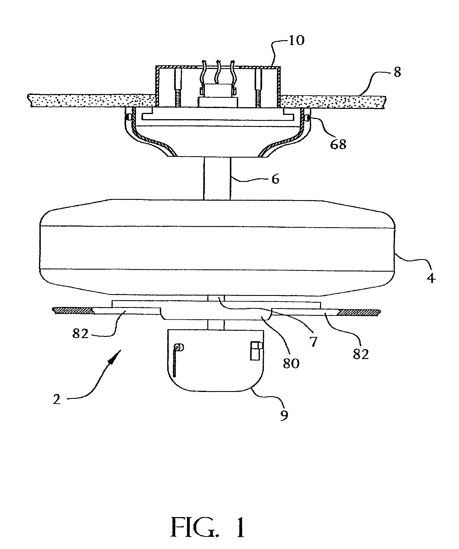
[0030]Referring to the drawings, where like numerals indicate like elements, and initially to FIG. 1, a ceiling fan is generally indicated by the numeral 2. Many of the fan elements are conventional, the particular type or design of these conventional elements not being material to the invention. These conventional elements include a drive housing 4 that encloses a drive motor (not shown), a down rod connecting shaft 6 which provides a conduit for electrical wires, a drive shaft 7, a switch housing 9, and fan blades 82. In the interests of simplicity, the fans shown in the drawings are described as being mounted on the underside of a horizontal ceiling, with the connecting shaft 6 extending vertically downwards and the fan blades 82 rotating in a horizontal plane. It should be understood, however, that the invention is not limited to that orientation.

[0031]As shown in FIG. 1, an electrical junction box 10 is recessed in a ceiling 8. The junction box 10 is of the type that supports a...


PUM


Abstract

Various forms of ceiling fan with easy install features are disclosed. The fans include an electrical quick connect device. The quick connect device includes a plug / receptacle configuration enabling the fan to easily connect to an electricity supply while providing the gravitational and rotational support required by the fan.

Description

CROSS-REFERENCE TO RELATED APPLICATIONS[0001]This application is a continuation in part of U.S. patent application Ser. No. 09 / 639,779, filed Aug. 16, 2000, now U.S. Pat. No. 6,464,524, which is a continuation of U.S. patent application Ser. No. 09 / 360,268, filed Jul. 26, 1999, now U.S. Pat. No. 6,146,191. This application also claims benefit of U.S. provisional patent application No. 60 / 299,635, filed Jun. 20, 2001. All of those applications are herein incorporated in their entirety.FIELD OF THE INVENTION[0002]The present invention is directed to the general field of ceiling fixtures, and to the more specific field of ceiling fans with features that make easier the tasks of hanging and electrically connecting the fan.BACKGROUND OF THE INVENTION[0003]The installation of a ceiling fan is a difficult task for a single installer. To install a conventional ceiling fan, the fan is lifted to just below the electrical junction box and held there while connecting the fan wires to the electr...

Claims


Application Information

Patent Timeline
Patent Type & Authority Patents(United States)
IPC IPC(8): H01R13/60F04D25/08F04D29/60F21V21/03H01R13/24H02G3/12H02G3/20
CPCF04D25/088F04D29/601H02G3/20H02G3/123F21V21/03H01R13/24H01R24/68H01R24/78H01R2103/00H01R23/10
Inventor KERR, JACK RUSSELL
Owner ANGELO FAN BRACE LICENSING
Why Eureka
Try Eureka