Eureka AIR delivers breakthrough ideas for toughest innovation challenges, trusted by R&D personnel around the world.

Flexible non-pneumatic tire

a non-pneumatic, flexible technology, applied in the field of tires, can solve problems such as gradual deradialisation, and achieve the effects of good overall operation of the load-bearing structure, excellent endurance, and excellent performan

Inactive Publication Date: 2006-02-07
CONCEPTION & DEV MICHELIN SA
View PDF16 Cites 95 Cited by
  • Summary
  • Abstract
  • Description
  • Claims
  • Application Information

AI Technical Summary

Benefits of technology

[0013]The invention proposes producing flexible joints which are independent of each other and separated from each other circumferentially, each flexible joint being integral, on the one hand, with a support element and, on the other hand, with the interconnection structure, in order to transmit the forces between the support elements and the interconnection structure. The advantageous operation of the tire proposed by the invention makes it possible to obtain good overall operation of the load-bearing structure while suitably decoupling its constituent elements, which is a guarantee of excellent endurance combined with excellent performance.

Problems solved by technology

During travel in normal operation of the tire, the penetration of the support elements into the contact area is somewhat retarded, which causes gradual deradialisation.

Method used


Image

  • Flexible non-pneumatic tire
  • Flexible non-pneumatic tire
  • Flexible non-pneumatic tire

Examples


Embodiment Construction

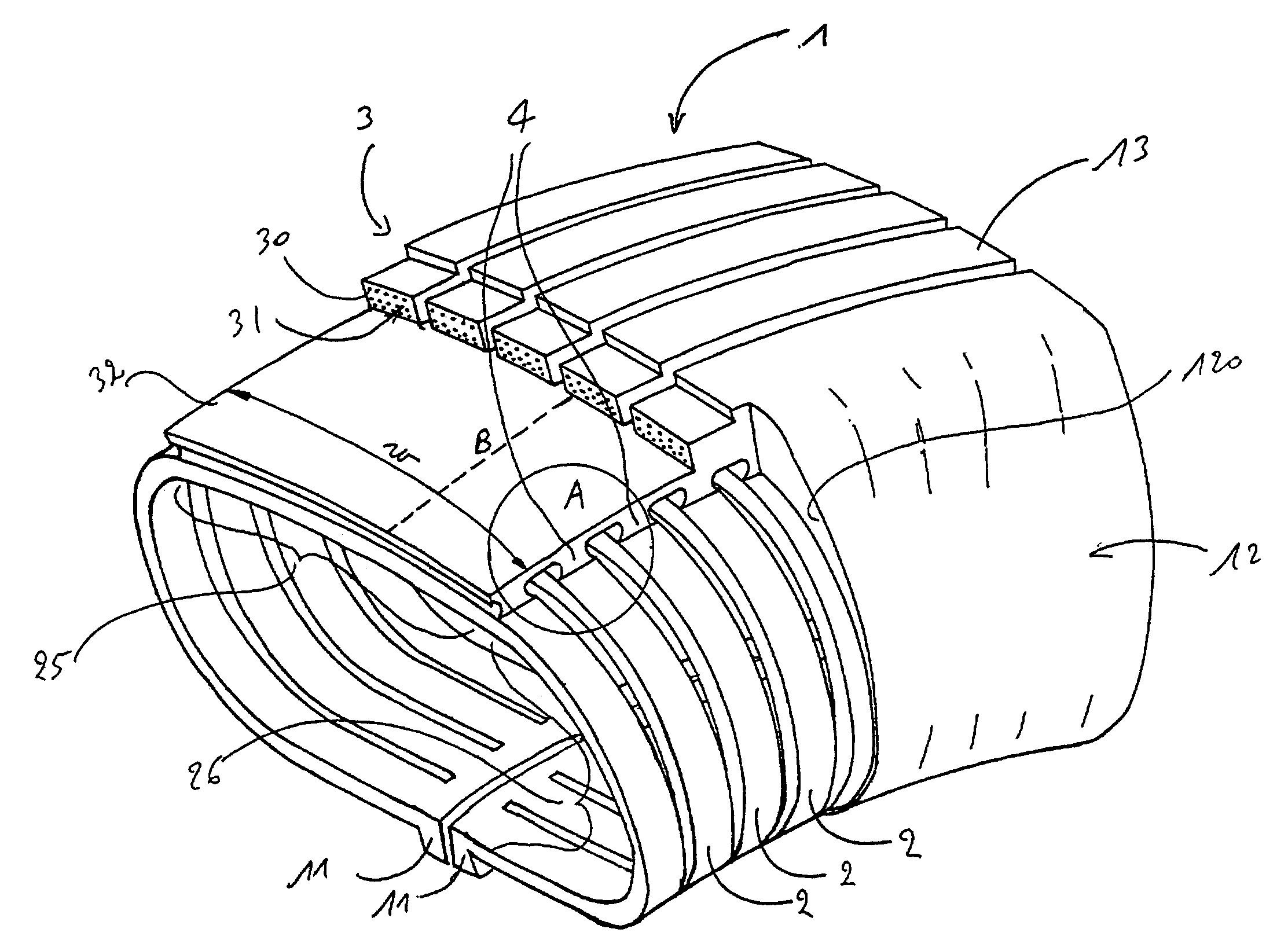
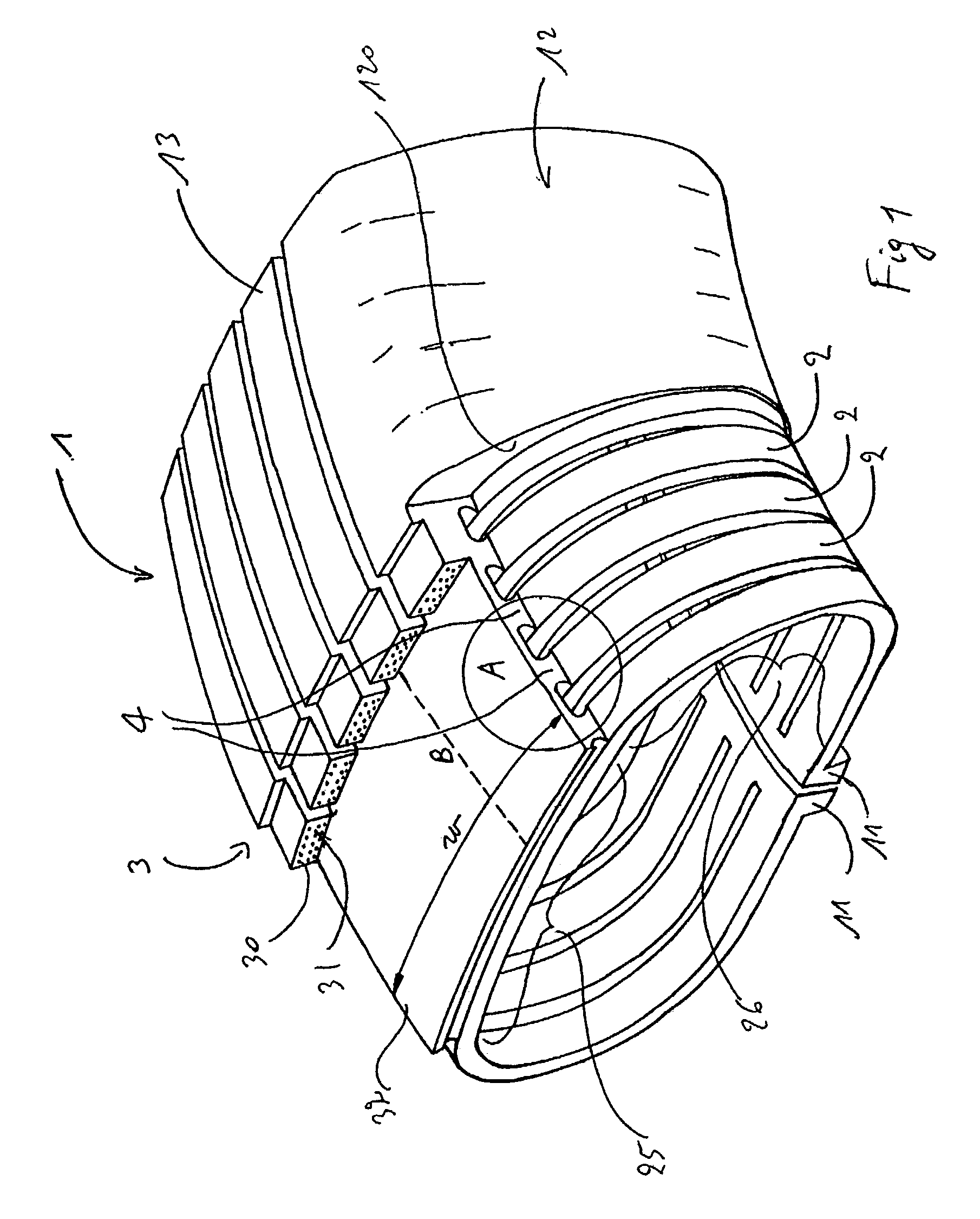
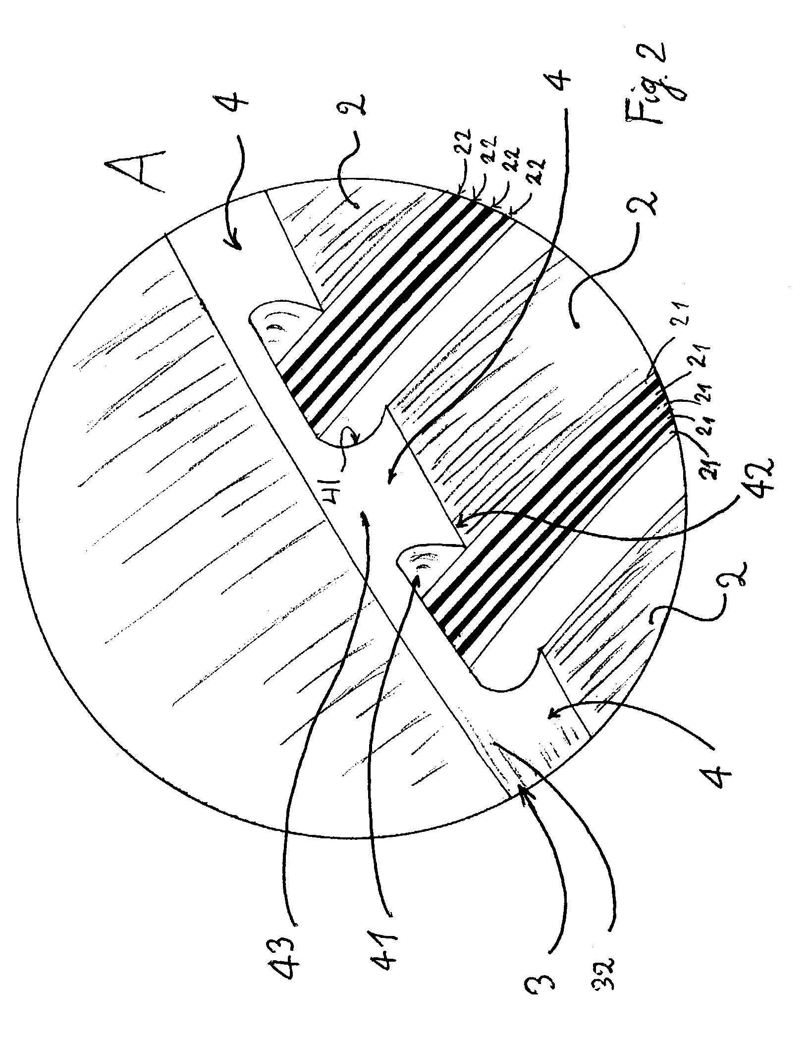
[0020]FIG. 1 illustrates an embodiment in which the profile of the tire defines a toric inner cavity of ovoid section. The non-pneumatic tire 1 comprises two axially separable fastening zones 11, two sidewalls 12 and a tread 13. The tread 13 is shown as comprising a plurality of parallel ribs; however this aspect is merely for illustrative purposes and is non-limitative. The sidewalls 12 are rounded and occupy the major part of the radial height of the tire 1. The load-bearing structure comprises support elements 2. The support elements 2 are circumferentially adjacent and each extends substantially radially and is continuous from one fastening zone 11 to the other. As can be seen in FIG. 2, each support element 2 comprised a stack of leaves 21 of composite material which are flexible and superposed with a layer of elastomer 22 interposed between the leaves 21. The bundle of leaves thus glued to one another forms a beam capable of being flexurally stressed. This aspect of the consti...


PUM


Abstract

A non-pneumatic tire comprises circumferentially-spaced support elements joined together by an interconnection structure with the interposition of flexible joints, so as to ensure good overall operation.

Description

BACKGROUND OF THE INVENTION[0001]1. The Field of the Invention[0002]The present invention relates to tires mounted on wheels and intended to be capable of bearing a substantial load without inflation pressure, referred to as non-pneumatic tires.[0003]2. The Related Art[0004]Patent application WO 00 / 37269, corresponding to U.S. patent application Ser. No. 09 / 466,524, filed Dec. 17, 1999, proposes such an elastic non-pneumatic tire. It describes a load-bearing structure essentially comprising a plurality of support elements arranged substantially radially, cyclically symmetrically all around the circumference of the tire. When the non-pneumatic tire described in patent application WO 00 / 37269 bears a load, a certain number of support elements present in the contact area are subjected to major flexing, which makes it possible for them to develop a force of taking up part of the load. An interconnection structure makes the support elements work together, transferring the stresses to the...

Claims


Application Information

Patent Timeline
Patent Type & Authority Patents(United States)
IPC IPC(8): B60C7/08B60C7/00B60C7/10B60C7/12B60C7/16B60C9/18
CPCB60C7/10B60C9/18B60C7/16B60C7/12
Inventor DELFINO, ANTONIOHINC, HENRYLAURENT, DANIEL
Owner CONCEPTION & DEV MICHELIN SA
Why Eureka
Eureka Blog
Learn More