
Slider having plural leading step-level slots

a step-level slot and slider technology, applied in the field of aerodynamic sliders, can solve the problems of adversely affecting the flying characteristics of the slider, adversely affecting the transducer transducer transducer transducer transducer, and accumulating particles and debris on the slider and on the transducer, etc., to achieve the effect of inhibiting fluid flow

Inactive Publication Date: 2006-01-24
SEAGATE TECH LLC
View PDF27 Cites 11 Cited by
  • Summary
  • Abstract
  • Description
  • Claims
  • Application Information

AI Technical Summary

Benefits of technology

[0009]An AAB slider has a leading edge generally impinging fluid flow due to movement of a medium relative to the slider. A transducer is supported by the slider adjacent a trailing edge. A cavity dam defines an air bear...

Problems solved by technology

Without these steps, the ABS may be too close to the disc to permit air to enter the region between the disc and the slider.
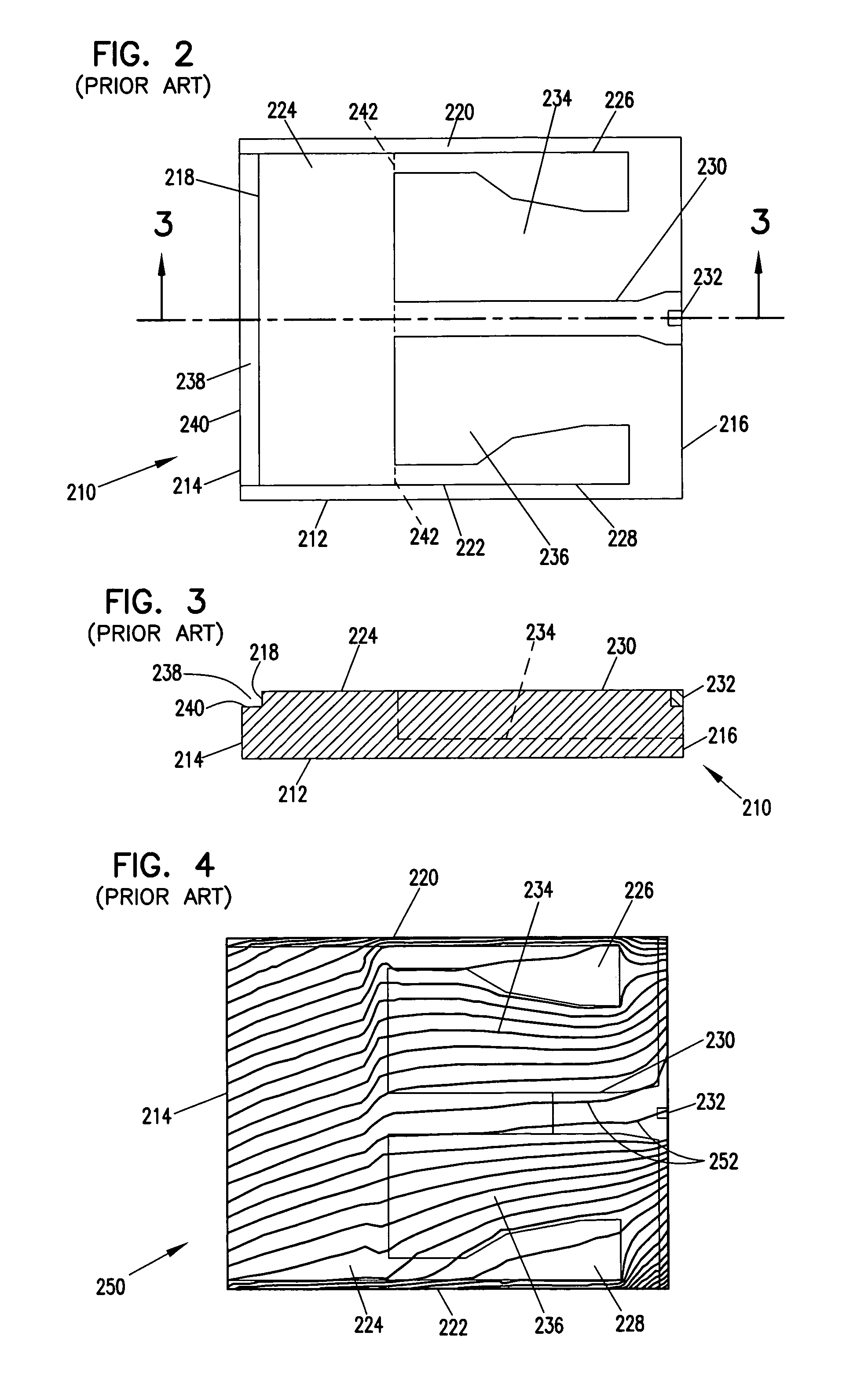
One problem of sliders is that particulate matter (particles and debris) may accumulate on the slider and on the transducer.
The accumulated particulate matter may adversely affect the flying characteristics of the slider, and may adversely affect the transducing properties of the transducers.
Moreover, if the accumulation of particulate matter becomes too great, the slider may drag the particulate matter against the media surface, thereby damaging the slider, transducer and / or disc.
In any case, damage may occur, resulting in a loss of data, and in worst cases a failure of the disc drive.
Particulate matter is particularly adverse to AAB sliders due to their low flying characteristics.
The airflow carries particulate matter, which accumulates on the transducer at the trailing edge, leading to head failure.
However, the low flying ABS also blocks airflow, thereby reducing pressurization of the air bearing surface and adversely affecting flying characteristics of the head.

Method used


Image

  • Slider having plural leading step-level slots
  • Slider having plural leading step-level slots
  • Slider having plural leading step-level slots

Examples


Embodiment Construction

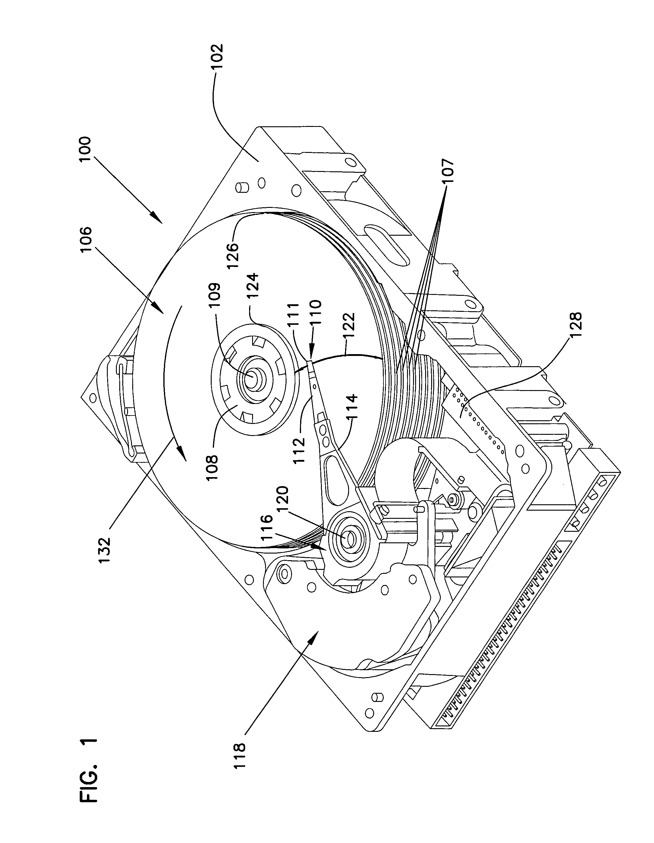
[0024]FIG. 1 is a perspective view of a disc drive 100 in which the present invention is useful. Disc drive 100 includes a housing with a base 102 and a top cover (not shown). Disc drive 100 further includes a disc pack 106, which is mounted on a spindle motor (not shown) by a disc clamp 108 for rotation in the direction of arrow 132. Disc pack 106 includes a plurality of individual discs 107, which are mounted for co-rotation about central axis 109. Each disc surface has an associated slider 110 that is mounted in disc drive 100 for communication with the confronting disc surface. Slider 110 is arranged to fly above the associated disc surface of an individual disc of disc pack 106, and carries a transducing head 111 arranged to write data to, and read data from, concentric tracks on the confronting disc surface. In the example shown in FIG. 1, sliders 110 are supported by suspensions 112 which are in turn attached to track accessing arms 114 of an actuator 116. Actuator 116 is dri...


PUM


Abstract

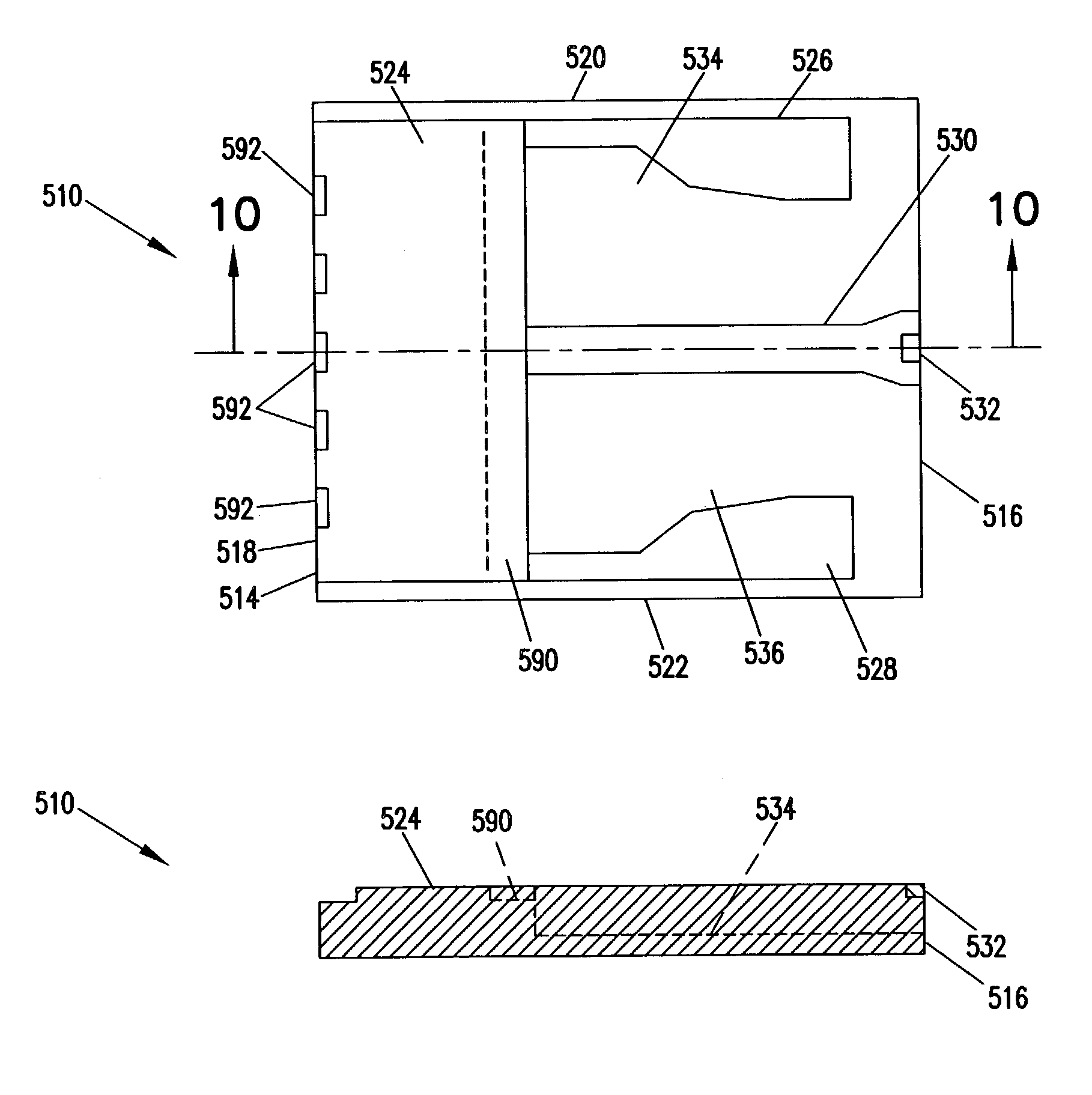
An AAB slider has a leading edge generally impinging fluid flow due to movement of a medium relative to the slider. A cavity dam defines a continuous air bearing surface that extends over a region between the sides of the slider and between at least one sub-ambient cavity and the leading edge. Step level slots in the air bearing surface at the leading edge admit fluid into the region of the air bearing surface. Side rails on the slider extend rearward from the cavity dam to form the sub-ambient cavity. The air bearing surface is characterized by the absence of a channel adjacent the leading edge that extends between the sides of the slider. A center rail extends rearward from the cavity dam to the trailing edge and supports a transducer. The arrangement is such that airflow to the transducer is minimized, thus minimizing particulate matter from accumulating on the trailing edge slider features, including the transducer.

Description

CROSS-REFERENCE TO RELATED APPLICATION[0001]This application claims priority of U.S. Provisional Application No. 60 / 357,576 filed Feb. 15, 2002 for “AAB Features to Improve Particle Insensitivity”.FIELD OF THE INVENTION[0002]This invention relates to aerodynamic sliders that position transducing heads relative to a movable medium, and particularly to proximity advanced air bearing (AAB) sliders used in disc drive data storage systems.BACKGROUND OF THE INVENTION[0003]In magnetic disc drive storage devices, digital data are written to and read from a thin layer of magnetizable material on surfaces of one or more rotating discs. Read and write operations are performed through read and write transducers that are carried on a slider body. The slider and transducers are sometimes collectively referred to as a head, and typically a single head is associated with each disc surface. Air is dragged by the disc due to rotation of the disc, generating a generally circular airflow pattern around...

Claims


Application Information

Patent Timeline
IPC IPC(8): G11B5/60G11B17/32G11B21/21
CPCG11B5/6082G11B5/6005G11B21/21
Inventor RAJAKUMAR, RAJAHANKAR
Owner SEAGATE TECH LLC
Learn More