
Optical fiber propagation time measurement

a technology of optical fiber and propagation time, which is applied in the field of optical fiber propagation time measurement, can solve the problems of inability to achieve two meters accuracy, limited measurement resolution, and high cost of conventional methods, and achieves the effects of low cost, high degree of accuracy, and simple method

Active Publication Date: 2006-01-24
JOHN FLUKE MFG CO INC
View PDF3 Cites 9 Cited by
  • Summary
  • Abstract
  • Description
  • Claims
  • Application Information

AI Technical Summary

Benefits of technology

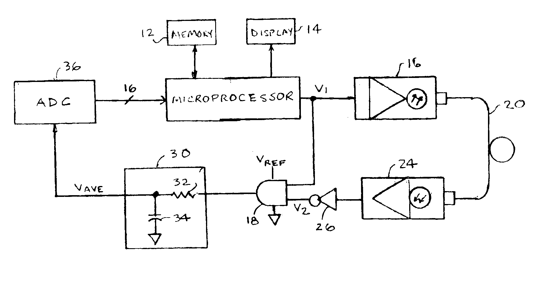
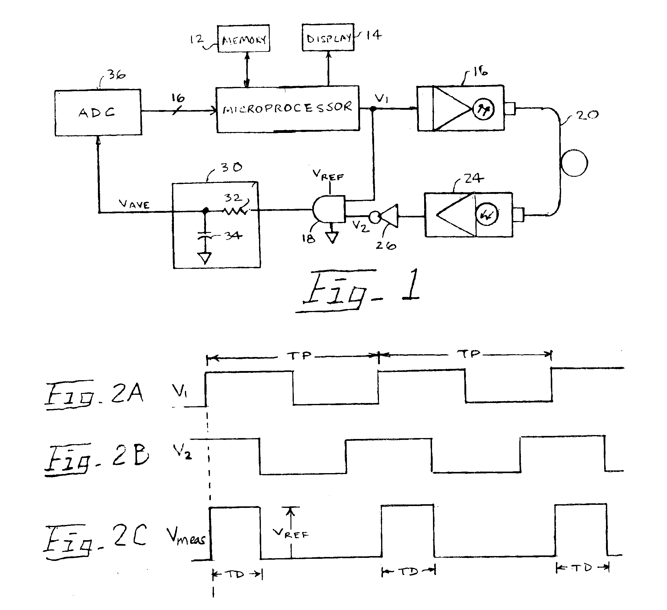
The present invention provides a simple and low-cost system for accurately measuring optical fibers. The system uses a light pulse that is sent into the fiber and detected at the other end. The detection circuitry creates a repetitive digital signal with a specific amplitude and width that corresponds to the time it takes for the light to propagate through the fiber. By measuring the average voltage of this signal, the system can accurately determine the length of the fiber. This invention can be used in fiber-optic measurement instruments such as optical power meters.

Problems solved by technology

Typically, conventional methods are expensive and rely on either high-speed counters or high-speed digital sampling to make the measurements, and therefore there is a limit to the measurement resolution, which in turn contributes to inaccuracies.
But for short fibers, an accuracy of ± two meters may be unacceptable.

Method used


Image

  • Optical fiber propagation time measurement
  • Optical fiber propagation time measurement

Examples


Embodiment Construction

[0011]Referring to FIG. 1 of the drawings, there is shown an optical fiber propagation time measurement circuit in accordance with the present invention. This circuit may suitably be a portion of a measurement instrument, such as an optical power meter. A microprocessor 10 may control several instrument functions, and it is shown connected to a memory 12 and a display device 14. A stimulus pulse output of microprocessor 10 is connected to both an optical transmitter 16, which converts voltage pulses into light pulses, and one input of a logic gate 18. The output of optical transmitter 16 is coupled via an optical coupler to the near end of a fiber under test (FUT) 20. The far end of FUT 20 is coupled via an optical coupler to a detector 24, which converts received light pulses to a voltage signal. The output of detector 24 is coupled through an inverter 26 to a second input of logic gate 18. The output of logic gate 18 is connected to a filter 30, which comprises a resistor 32 and i...


PUM

PropertyMeasurementUnit
refractive indexaaaaaaaaaa
lengthaaaaaaaaaa
time periodaaaaaaaaaa

Abstract

An optical fiber propagation time measurement circuit. A light pulse is iteratively transmitted into a near end of a fiber under test (FUT) at a predetermined frequency and detected at a far end of the FUT after a propagation time. A repetitive propagation signal having a predetermined amplitude and a width corresponding the propagation time is developed by detection circuitry. The d.c. voltage average of the propagation signal is determined and used to compute the propagation time since the ratio of the d.c. voltage average to the predetermined amplitude is equal to the ratio of the propagation time to the period of the light pulses.

Description

BACKGROUND OF THE INVENTION[0001]This invention relates generally to measurement of optical fibers, and in particular to measurement of optical fiber propagation time measurement.[0002]It is well known by those skilled in the art that the time required for light to propagate through the length of an optical fiber is dependent upon the refractive index of the fiber and the wavelength of the light being transmitted. For a commercial grade fused silica optical fiber found in a conventional fiberoptic network, the refractive index is roughly 1.49 and the propagation time is roughly 5.0 ns / m (nanoseconds per meter). There are many well known methods for determining the length of optical fibers and measuring the time of light propagation down a fiber. Instruments such as time-domain reflectometers, for example, are capable of measuring both length and propagation time and displaying a graph of the resultant measurement. Typically, conventional methods are expensive and rely on either high...

Claims


Application Information

Patent Timeline
Patent Type & Authority Patents(United States)
IPC IPC(8): G01N21/00G01M11/00
CPCG01M11/332
Inventor WHITE, BRUCE T.
Owner JOHN FLUKE MFG CO INC
Learn More