
Vibration correcting device, lens barrel, and optical device

a vibration correction and lens barrel technology, applied in the field of image vibration correction devices, can solve the problems of harmfully affecting the drive of the shift member, difficult to reduce the rigidity of the flexible substrate, and difficult to reduce the elastic force in the optical axis direction to be generated on the flexible substrate to a permissible level, so as to reduce the frictional force of the drive, prevent the influence of the elastic force in the optical axis direction of the flexible substrate, and improve the effect of optical performan

Active Publication Date: 2006-01-10
CANON KK
View PDF21 Cites 45 Cited by
  • Summary
  • Abstract
  • Description
  • Claims
  • Application Information

AI Technical Summary

Benefits of technology

The solution enables enhanced optical performance with reduced frictional forces, improved accuracy in vibration correction, and the ability to downsize the device without compromising image stabilization, effectively addressing the limitations of previous technologies.

Problems solved by technology

However, if a lens barrel is downsized, a space for locating a vibration correcting device main body or a flexible substrate connecting the fixed member and shift member is remarkably limited, and as a result, it becomes difficult to sufficiently lower the rigidity of the flexible substrate.
Therefore, in U.S. Pat. No. 5,602,675, it is difficult to lower an elastic force in the optical axis direction to be generated on the flexible substrate to a permissible level by only contrivance in the shape and arrangement of the flexible substrate.
Therefore, in U.S. Pat. No. 6,112,028, even if the shift member is pressed in the optical axis direction by a proper force while using a magnetic attractive force, due to unevenness in the elastic force in the optical axis direction of the flexible substrate, the pins of the shift member are excessively pressed into the slots and resistance greatly increases, or to the contrary, pressing by means of the magnetic attractive force is canceled, and this harmfully influences the drive of the shift member.
However, since the ball rolls at the position at which the ball is held by the holding member, sliding frictional forces are generated between the ball and fixed member and between the ball and shift member.
Therefore, the pressing force of a spring for eliminating looseness is limited to be at a minimum level required for holding the ball, so that the shift member separates from the ball due to slight acceleration in the optical axis direction resulting from an inertial force exceeding this pressing force applied to the shift member, and the deterioration in optical performance due to tilt of the vibration correcting lens group and noise such as a ball striking sound becomes a problem.
The prevention of rotation of the shift member about the optical axis by means of a spring relies on the pulling force of the spring, so that the rotation cannot be completely stopped, and the force can only suppress the rotation.
Therefore, depending on the positional relationship between the force generating position at which the drive means generates a shifting drive force and the center of gravity of the shift member, or the connected position and shape of the flexible substrate connected to a coil on the shift member, the shift member rotates about the optical axis in accordance with the shifting drive, and the drive of the vibration correcting lens group to a correct position for vibration correction becomes impossible.

Method used


Image

  • Vibration correcting device, lens barrel, and optical device
  • Vibration correcting device, lens barrel, and optical device
  • Vibration correcting device, lens barrel, and optical device

Examples


Embodiment Construction

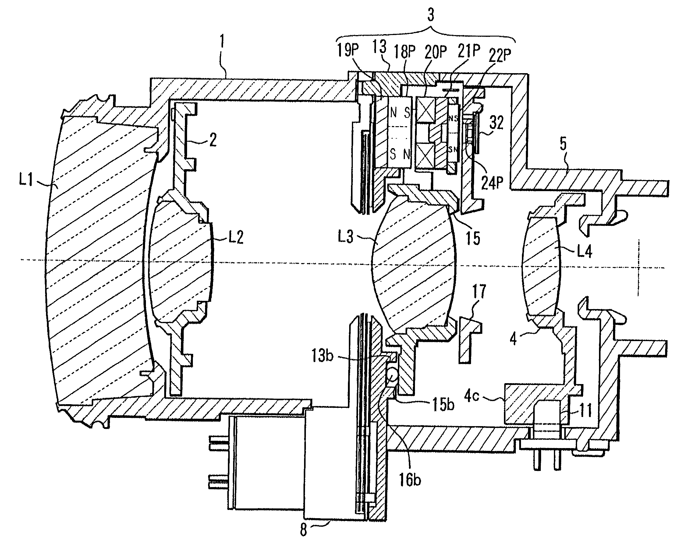
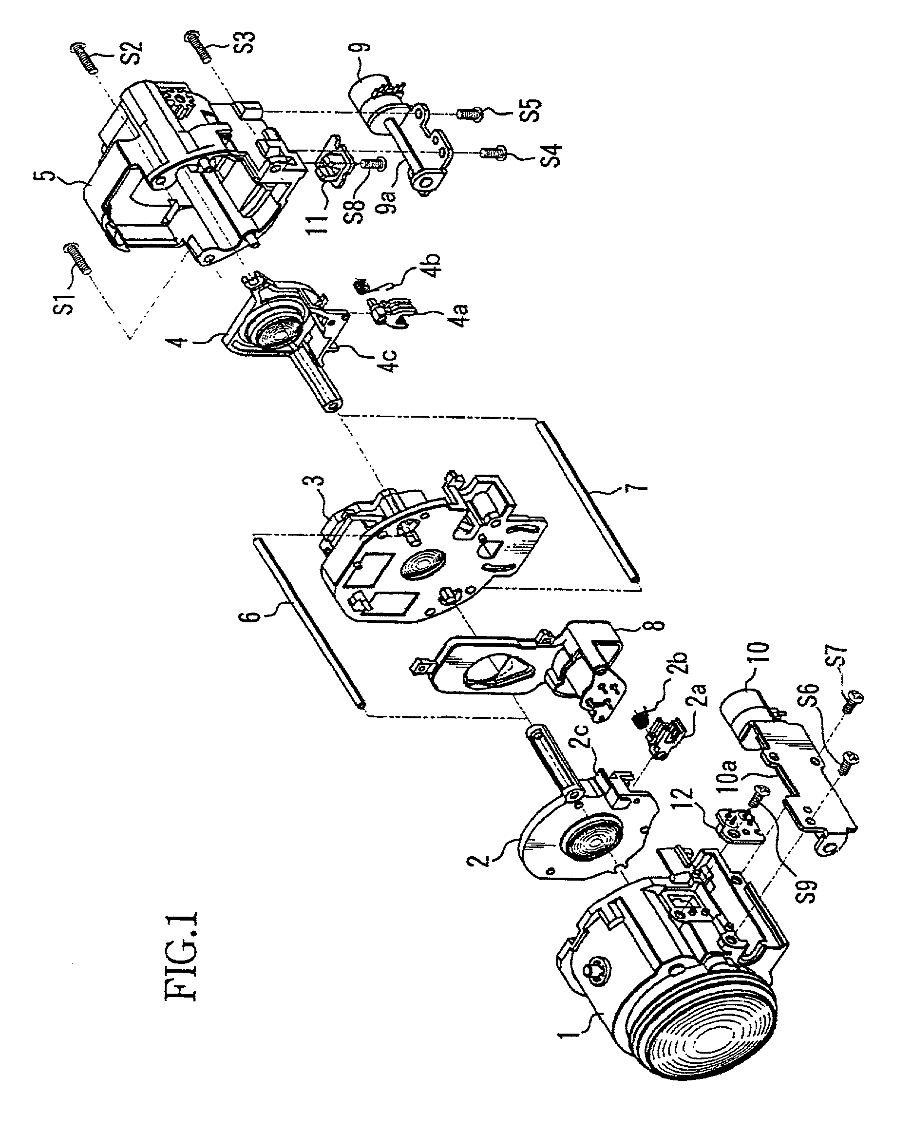
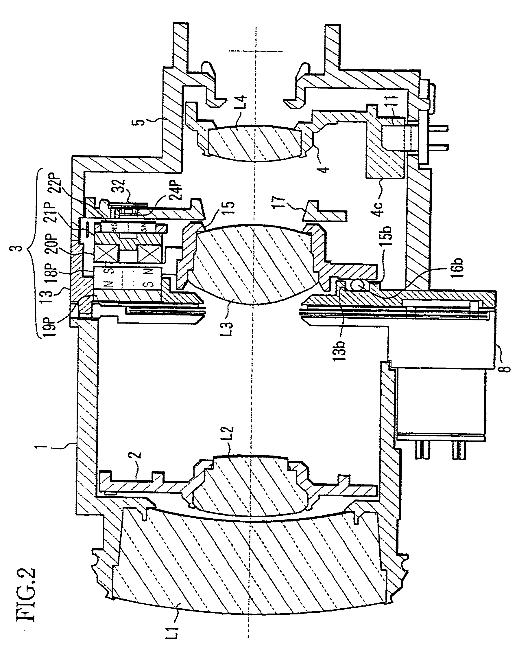
[0114]FIG. 1 and FIG. 2 show the construction of a lens barrel with a vibration correcting device of an embodiment of the invention. FIG. 1 shows the exploded perspective view of the lens barrel, and FIG. 2 shows the sectional view of the lens barrel. This lens barrel is used for a shooting device such as a video camera.

[0115]The optical system of this lens barrel is a zooming optical system composed of four groups, that is, a positive lens component, negative lens component, positive lens component, and positive lens component in order from the subject or observing object side.

[0116]L1 shows a fixed first lens group, L2 shows a second lens group which moves in the optical axis direction to carry out zooming operation, L3 shows a third lens group (vibration correcting lens: hereinafter referred to as shift lens) which moves within the optical axis orthogonal plane to carry out vibration correcting operation, and L4 shows a fourth lens group which moves in the optical axis direction ...


PUM


Abstract

An optical device with an imaging device for forming an image of a subject with a lens device includes a lens unit, a movable member making the lens unit movable within a plane orthogonal to the optical axis of the lens unit, an image pickup device imaging the subject image formed by the lens device, a fixed member limiting the movement of the movable member in the optical axis direction, at least three balls rolling between the movable and fixed member, a vibration detecting unit, and pitch and yaw direction drive units for driving the movable member in the pitch and yaw directions within the optical axis orthogonal plane, respectively. The pitch and yaw direction drive units press the movable member toward the fixed member side by means of magnetic pressing forces caused by magnetic attractive action between drive magnets and yokes.

Description

BACKGROUND OF THE INVENTION[0001]1. Field of the Invention[0002]The present invention relates to an image vibration correcting device for shifting a lens within an optical axis orthogonal plane to correct image vibration due to so-called hand movements, and for example, a vibration correcting device suitable for being installed in a lens barrel, or a imaging device such as a video camera, digital still camera or the like, or an observation device such as binoculars, astronomical telescope or the like.[0003]2. Description of the Related Art[0004]In order to prevent image vibration due to hand movements or the like which is easily caused when shooting in a hand-held condition, various devices have been proposed for realizing vibration correction by detecting vibration information of a camera or binoculars and optically canceling the vibration based on the detection results.[0005]For example, in U.S. Pat. No. 6,112,028 (Japanese Laid-Open No. 305277 of 1999), a so-called shift-method v...

Claims


Application Information

Patent Timeline
Patent Type & Authority Patents(United States)
IPC IPC(8): H04N5/228H04N23/40G03B5/00
CPCG03B5/00H04N5/23248G02B27/646H04N5/23287H04N5/23258G03B2217/005G03B2205/0015G03B2205/0069H04N23/68H04N23/6812H04N23/687
Inventor NOGUCHI, KAZUHIRO
Owner CANON KK
Learn More