
Platen for an injection molding machine, and two-platen injection molding machine equipped with such a platen

a technology of injection molding machine and platen, which is applied in the fields of butchering, food shaping, food science, etc., can solve the problems of their destruction

Inactive Publication Date: 2006-01-10
MANNESMANN PLASTICS MACHINERY
View PDF15 Cites 29 Cited by
  • Summary
  • Abstract
  • Description
  • Claims
  • Application Information

AI Technical Summary

Benefits of technology

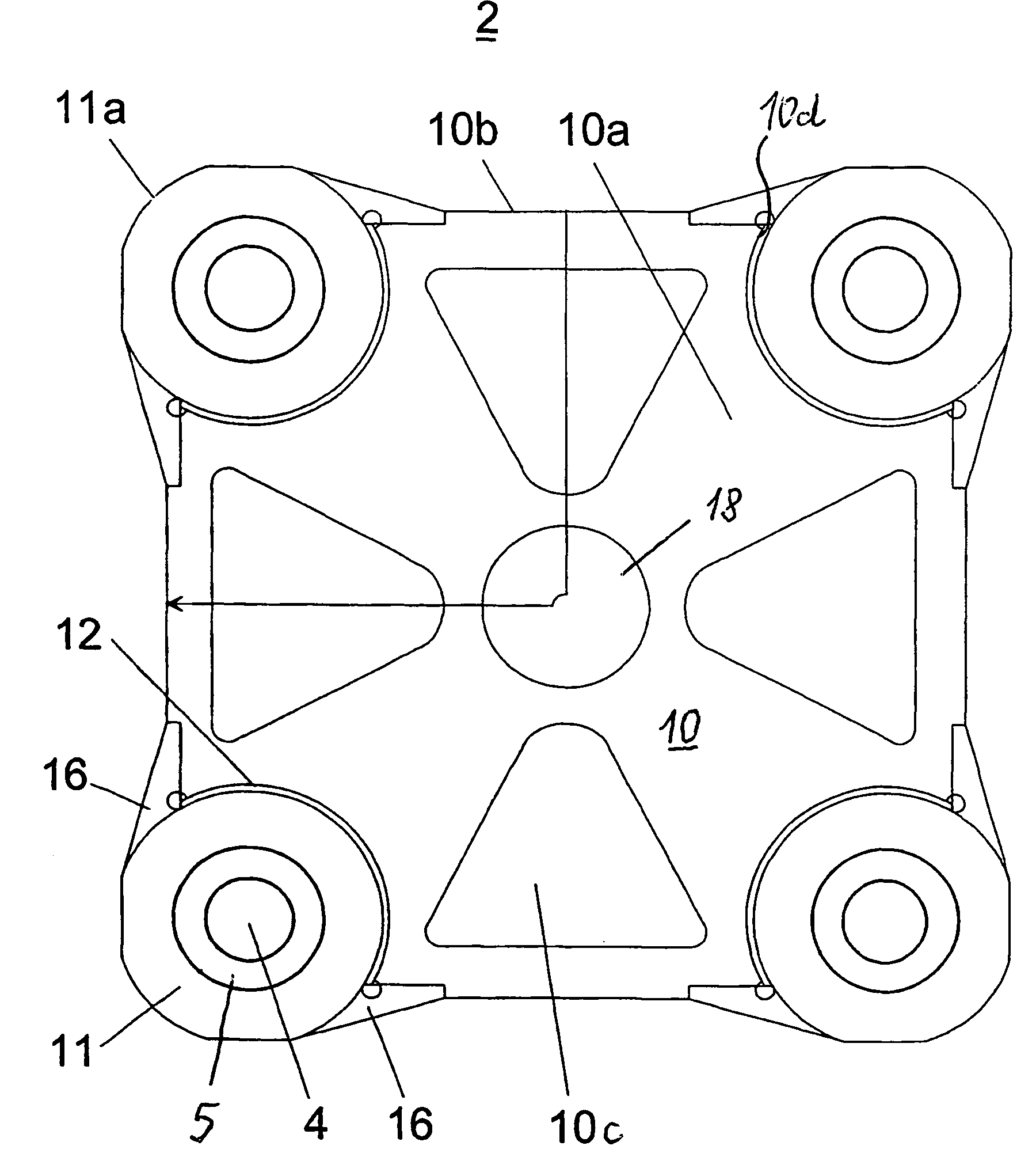
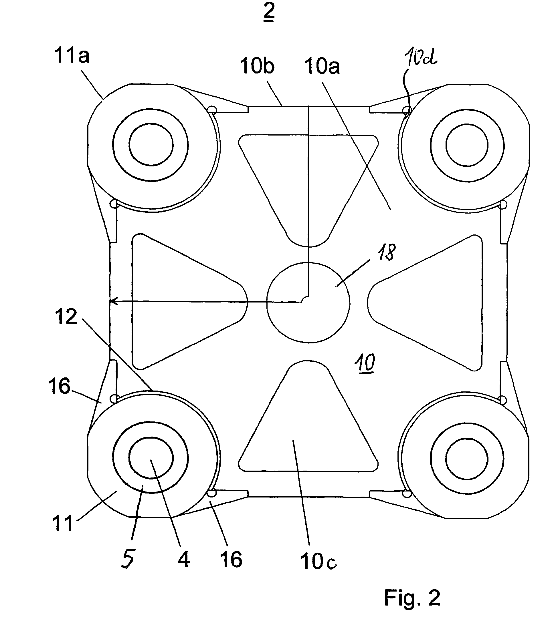
[0009]The present invention resolves prior art problems by providing an elastic connection between the center area and the sleeve through separation of the stiff center area from the elastic, quasi resilient support of the sleeves in the center area. The elastic connection can be implemented by providing between the center area and the sleeves a transition zone which is comprised of an annular gap to define a clearance between the center area and the sleeves and an annular bridge to connect the sleeves to the center area. Suitably, the ring-shaped gap has a depth which is greater than half a thickness of the center area, thereby enabling an adjustment of the desired elasticity.
[0010]According to another feature of the present invention the center area and the sleeves may be made in one piece, suitably of cast steel or gray cast iron. In this way, the platen can be made in a simple manner.
[0012]A platen according to the present invention is especially useful for plastics injection molding machines without tie bars, whereby the platens are connected via the holding and / or guiding elements, placed in the openings of the sleeves, with the normally U-shaped machine frame. This type of suspension of the platen in the form of an axis-less hinge effectively prevents the limb of the U-shaped machine frame to give way, when subjected to the clamping force, and thus maintains a parallelism of the platens.
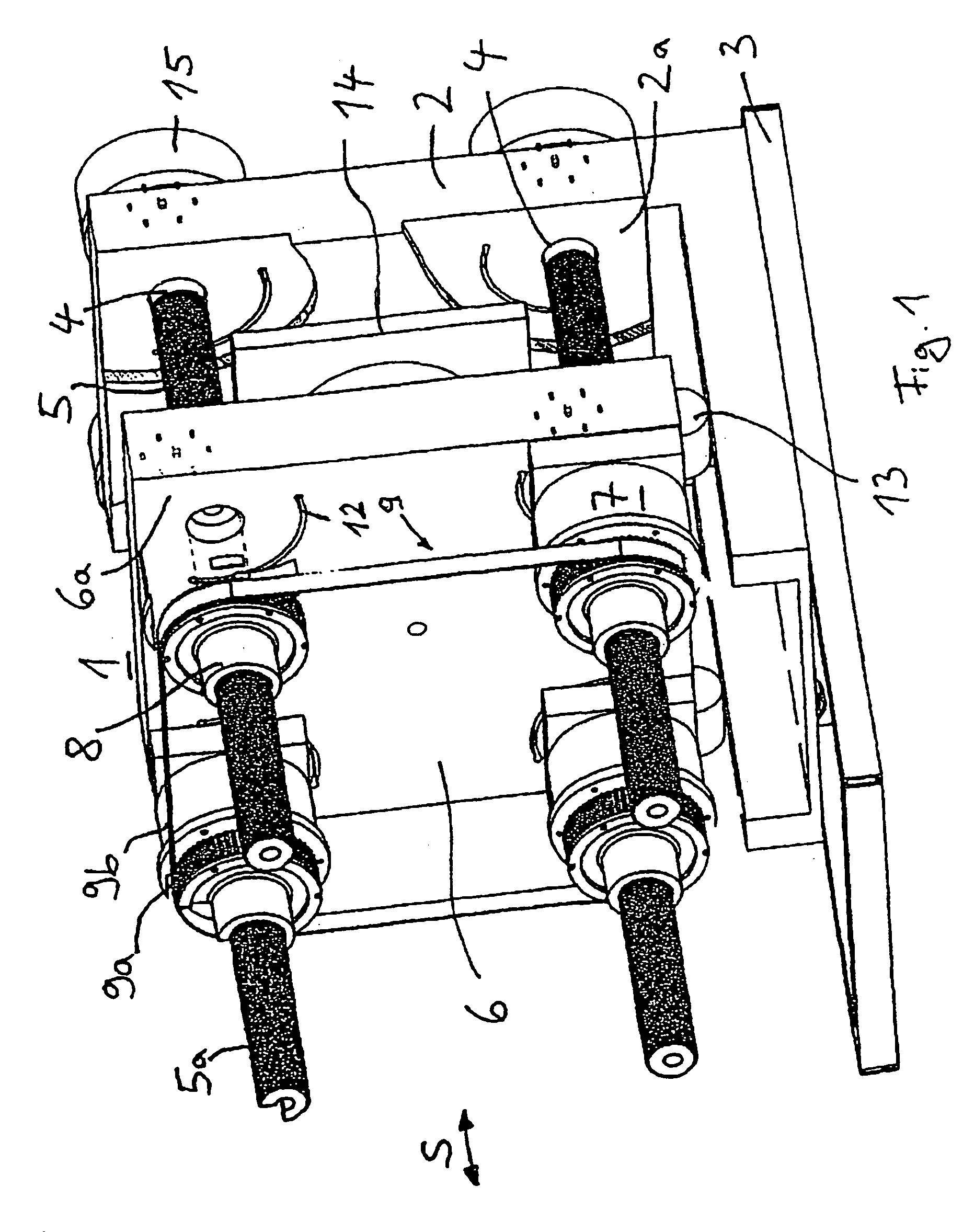
[0016]Suitably, the spindle mechanisms are constructed as ball screw mechanisms. This is desired because they run substantially free of friction and thus generate little noise and require little maintenance.
[0017]According to another feature of the present invention, the clamping unit may include a piston and cylinder unit for applying a clamping force onto the half-molds. In this way, the spindle mechanisms are used exclusively for opening and closing the half-molds and not required to apply the required clamping force.

Problems solved by technology

A tilting or deformation of the platens during application of the clamping force is accompanied by a bending of the spindles which are thus subject to increased wear, ultimately resulting in their destruction.

Method used


Image

  • Platen for an injection molding machine, and two-platen injection molding machine equipped with such a platen
  • Platen for an injection molding machine, and two-platen injection molding machine equipped with such a platen
  • Platen for an injection molding machine, and two-platen injection molding machine equipped with such a platen

Examples


Embodiment Construction

[0022]Throughout all the Figures, same or corresponding elements are generally indicated by same reference numerals. These depicted embodiments are to be understood as illustrative of the invention and not as limiting in any way. It should also be understood that the drawings are not necessarily to scale and that the embodiments are sometimes illustrated by graphic symbols, phantom lines, diagrammatic representations and fragmentary views. In certain instances, details which are not necessary for an understanding of the present invention or which render other details difficult to perceive may have been omitted.

[0023]Turning now to the drawing, and in particular to FIG. 1, there is shown a schematic perspective view of a clamping unit 1 of a horizontal two-platen injection molding machine for plastics. The injection molding machine includes a machine bed 3, a fixed platen 2, which is secured upright onto the machine bed 3 and carries a half-mold of a molding tool 14, and a moving pla...


PUM

PropertyMeasurementUnit
areaaaaaaaaaaa
thicknessaaaaaaaaaa
perimeteraaaaaaaaaa

Abstract

A platen of an injection molding machine includes a plate-shaped center area having corners, each corner formed with a recess. A plurality of sleeves is received in the recesses of the center area and defines bores for accommodation of column-like holding and / or guide elements. The sleeves have an outer surface in confronting relationship to the center area and are configured for only partial connection to the center area, thereby establishing an elastic connection between the center area and the sleeves.

Description

CROSS-REFERENCES TO RELATED APPLICATIONS[0001]This application is a continuation of prior filed copending PCT International application no. PCT / EP02 / 04913, filed May 4, 2002, which designated the United States and on which priority is claimed under 35 U.S.C. §120, the disclosure of which is hereby incorporated by reference.[0002]This application claims the priority of German Patent Application, Serial No. 101 23 104.0, filed May 12, 2001, pursuant to 35 U.S.C. 119(a)–(d), the disclosure of which is incorporated herein by reference.BACKGROUND OF THE INVENTION[0003]The present invention relates to a platen of an injection molding machine. The present invention further relates to a two-platen injection machine equipped with such a platen.[0004]U.S. Pat. No. 5,593,711 discloses a platen for use in a plastics injection molding machine, with the platen including a base plate, a frustoconical center part, and a front plate in parallel relationship to the base plate for carrying a molding t...

Claims


Application Information

Patent Timeline
Patent Type & Authority Patents(United States)
IPC IPC(8): B29C45/64B29C45/17B29C45/66
CPCB29C45/66B29C45/1744
Inventor FISCHBACH, GUNTHERBECKER, KLAUSLEGEWIE, GUIDO
Owner MANNESMANN PLASTICS MACHINERY
Learn More