
Forced-air zone climate control system for existing residential houses

a forced air and climate control technology, applied in ventilation systems, heating types, domestic cooling apparatuses, etc., can solve the problems of difficult retrofitting, limited function and benefit, and inability to provide practical solutions for easy retrofitting, etc., to achieve easy installation, low cost, and low cost

Active Publication Date: 2006-01-10
EMME E2MS
View PDF15 Cites 382 Cited by
  • Summary
  • Abstract
  • Description
  • Claims
  • Application Information

AI Technical Summary

Benefits of technology

[0024]An objective of this invention is an improved zone climate control system that provides better comfort because the temperature in each room is monitored and the airflow through each air duct is controlled by a control processor that also controls the HVAC equipment. In effect, each room has its own thermostat.
[0026]Another objective of this invention is an improved zone climate control system that is low cost. The invention uses an optimized combination of mature electronics technology, simple mechanics, and software to reduce the total system cost.
[0027]Another objective of this invention is an improved zone climate control system that reduces energy use. Individual rooms can be heated and cool according to independent minute-by-minute and day-by-day schedules that match occupancy and activity.
[0028]Another objective of this invention is an improved zone climate control system that measures the relative energy used to condition each room. This information is used to diagnose insulation and HVAC equipment problems, providing the information needed to make cost-effective decisions about improvements in house or HVAC equipment. This information is also used to predict the change in energy usage caused by a change in the temperature schedule of a room, enabling the occupant to make informed decisions about comfort versus energy usage.
[0029]Another objective of this invention is an improved zone climate control system that the house occupants find easy to use. An intuitive, graphical application running on personal data assistant (PDA such as a Palm) or a personal computer is used to specify the temperature schedules for each room for each day, and to specify the function assigned to a push button on the wireless thermometers. Other push buttons on the thermometers provide simple methods for the most common adjustments such as temporarily changing the room temperature.SUMMARY OF INVENTION
[0030]Briefly described, this invention is an improved zone climate control system for installation in existing residential forced air HVAC systems. The system is low cost and installation is quick, easy, and non-intrusive. The system provides independent room-by-room, minute-by-minute, and day-by-day temperature control. Pneumatic airflow control devices are installed in each air vent and the controlling air tubes are pulled through the existing air ducts to the central discharge plenum so that the air ducts are not accessed, disassembled, or modified in any other way during installation. Battery powered wireless thermometer devices are placed in each room to report the local temperature and provide programmable one-button functions for controlling temperatures. A control processor mounted on the plenum controls the existing HVAC equipment and airflow control devices while monitoring plenum pressure and plenum temperature to control the temperature in each room following temperature schedules assigned to the rooms. A PDA or PC application is used to specify and assign minute-by-minute temperature schedules to each room for each day. The relative energy used to condition each room is stored and displayed so that the occupant can make informed decision between comfort and energy savings and identify correctable problems with the HVAC equipment or house insulation.

Problems solved by technology

Maintaining comfortable temperatures requires constant adjustment, or may not be possible.
These temperature control problems are well known to HVAC suppliers, installers, and house occupants.
These conventional systems are difficult to retrofit and provide limited function and benefit.
A few systems have proposed thermostats for each room and airflow control devices for each air vent, but no practical solution for easy retrofit has been disclosed.
Typical residential HVAC systems are designed to produce one fixed rate of heating and cooling, so adapting the existing systems to provide heating or cooling for only one or two rooms is difficult.
They have been widely adopted because they are expensive, difficult and intrusive to install in most existing houses, and provide limited utility and benefit compared to their cost and inconvenience.
The devices are mechanically complex, each with a radio receiver, servo motor, and multiple mechanical louvers.
Another embodiment is described that uses wires connected to a central control unit to control the airflow control devices, adding complexity to the installation process.
The devices are expensive and have no shared mechanisms for control or activation to reduce the cost of the multiple devices required.
A cited advantage of the system is it does not have sensors inside the ducts, so the system cannot make control decisions based on plenum pressure or plenum pressure, therefore excessive noise and temperatures may occur for some settings of the airflow control devices.
The thermostats and common controller have complex interfaces with limited functionality making the system difficult to use.
This system is expensive and difficult to retrofit.
These airflow control devices do not provide a way for non-intrusive installation.
This devices uses substantial power and battery life is limited.
Since the blower for inflating the bladder is located at the air vent, noise from the blow is a problem which the inventor provides a muffler to help control.
Each bladder is an independent unit and there is no sharing of components for controlling or powering, so there are no savings when many airflow devices are used in a zone control system.
This system is difficult to retrofit and does not exploit selective circulation to equalize temperatures.
This system is not practically adaptable to a residential system.
This system is designed for large commercial buildings and is no practically adaptable for retrofit to a house.
The cost and complexity of a full functioning thermostat is duplicated for each device.
The number of input buttons and the display capabilities at each devices is limited so programming is complex and functionality is limited.
This device provides no method for entering commands at the wireless thermometer and uses a fixed slow rate of reporting the temperature stored at the wireless thermometer.
The system is not adapted for use with a zone control system.
The control architecture requires reliable two way communication and is not practical for battery powered operation.
The describes system cannot operate with infrequent and unreliable transmissions from the wireless thermometers and is not adaptable for low cost installation into existing residential HVAC systems.
Using this type of interface to program multiple temperature schedules for multiple zones would take great effort and is complex.
This device is not practically adaptable for use in a room-by-room zone control system for a house.
It provides no means for saving temperature schedules or grouping temperature schedules into temperature programs for the entire house.
The device is not practical for adapting to a residential house.
The method prorate the total based on time and does not account for different rates of energy use by each unit.
The method does not provide accurate results when each unit draws energy at different rates from the common source, and is not adaptable to a residential zone controlled forced air HVAC system.
This method is not adaptable to air ducts because air duct are variable size, have irregular bends and corners, and are designed to withstand very small pressure differences.
The prior art individually or in combination does not provide a practical means for providing a zone control system or retrofit to existing HVAC residential buildings and homes.
The control systems are complex and difficult to control so the occupants are not able to get full benefit from zone control.
Prior systems provide no means for diagnosing energy use to identify HVAC equipment of building problems that can be cost effectively repaired.

Method used


Image

  • Forced-air zone climate control system for existing residential houses
  • Forced-air zone climate control system for existing residential houses
  • Forced-air zone climate control system for existing residential houses

Examples


Embodiment Construction

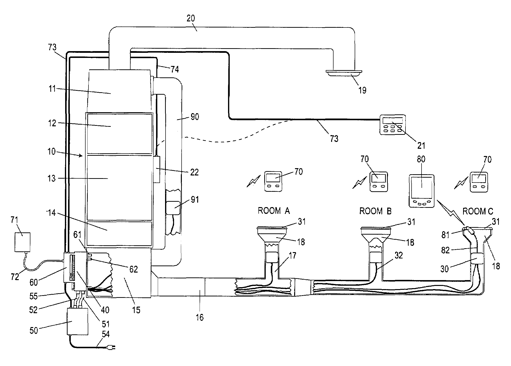
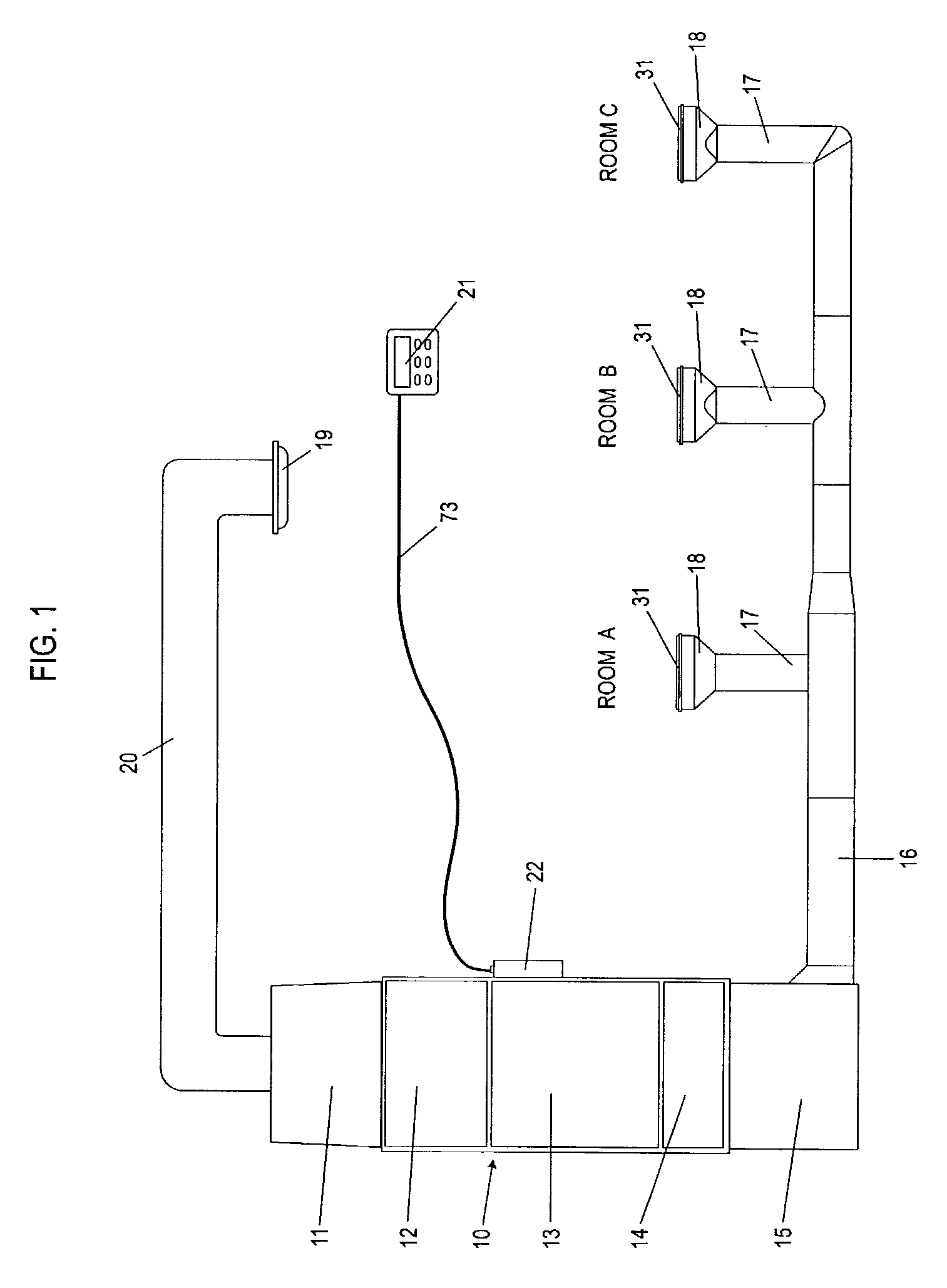
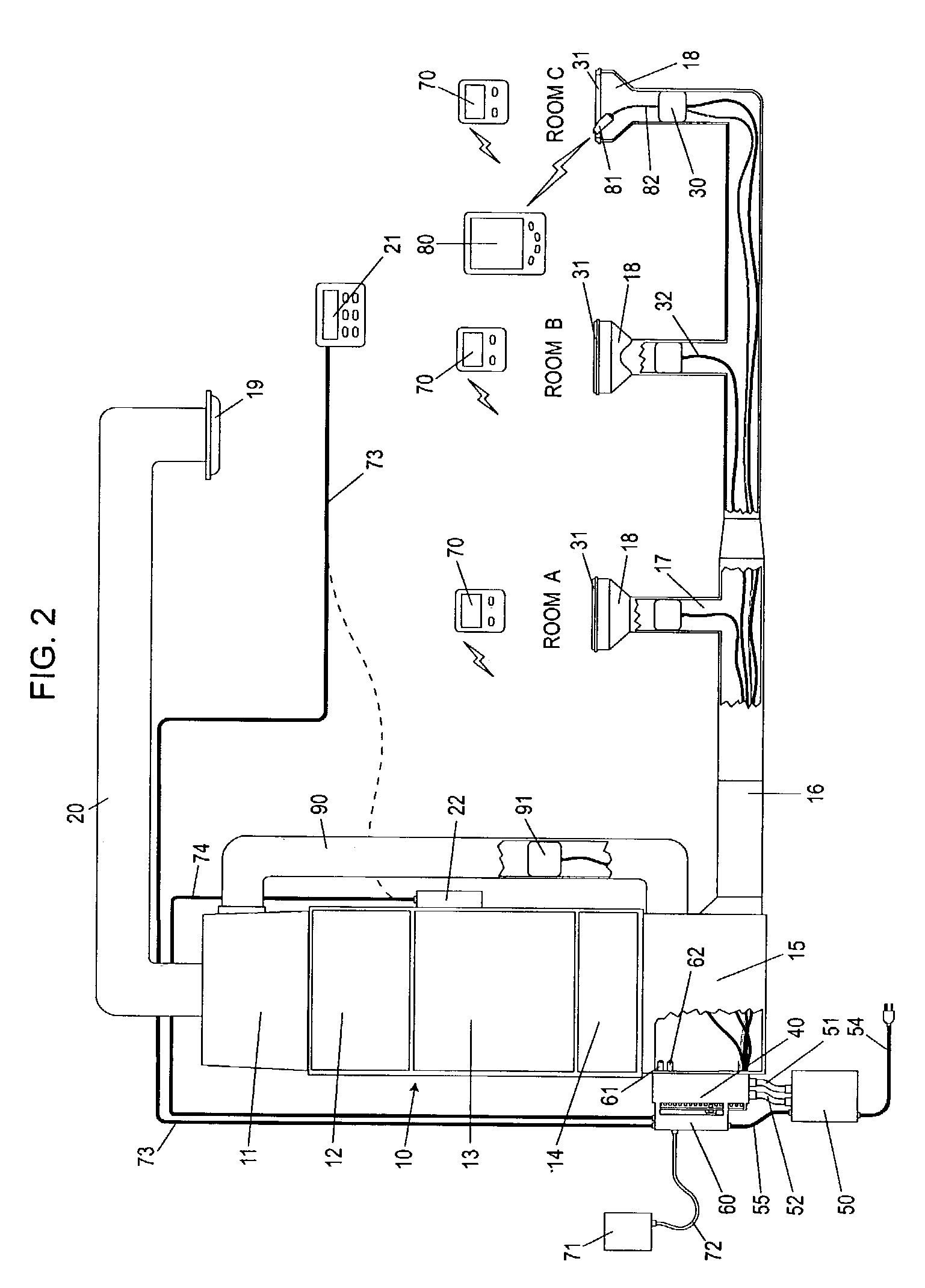
[0059]FIG. 1 is a block diagram of a typical forced air system. The existing central HVAC unit 10 is typically comprised of a return air plenum 11, a blower 12, a furnace 13, an optional heat exchanger for air conditioning 14, and a conditioned air plenum 15. The configuration shown is called “down flow” because the air flows down. Other possible configurations include “up flow” and “horizontal flow”. A network of air duct trunks 16 and air duct branches 17 connect from the conditioned air plenum 15 to each air vent 18 in room A, room B, and room C. Each air vent is covered by an air grill 31. Although only three rooms are represented in FIG. 1, the invention is designed for larger houses with many rooms and at least one air vent in each room. The conditioned air forced into each room is typically returned to the central HVAC unit 10 through one or more common return air vents 19 located in central areas. Air flows through the air return duct 20 into the return plenum 11.

[0060]The e...


PUM

PropertyMeasurementUnit
pressureaaaaaaaaaa
radio frequencyaaaaaaaaaa
frequencyaaaaaaaaaa

Abstract

A low cost and easy to install zone climate control system for retrofit to an existing forced air HVAC system, that provides independent minute-by-minute, day-by-day, and room-by-room climate control, including easy to use methods for specify temperature schedules and providing local temperature control, and providing detailed energy use information so occupants can make informed cost versus comfort decisions.

Description

BACKGROUND OF INVENTION[0001]This invention relates to controlling residential forced air HVAC systems, specifically an improved zone climate control system, for installation in an existing HVAC system, that is less expensive, easier to install, and provides more utility than the prior art, such that a plurality of rooms in the residence each have independent temperature regulation according to predetermined temperature schedules and locally entered temperature commands, and such that the air in each said room is heated or cooled according to the occupancy and the activity in said room, whereby improving the comfort of the occupants and reducing the energy used to heat or cool the residence.[0002]The majority of single-family houses in the United States have forced air central heating systems. Many of these also have air conditioners that use the same air distribution system. These heating, ventilation, and air conditioning (HVAC) systems are typically controlled by a single, centra...

Claims


Application Information

Patent Timeline
Patent Type & Authority Patents(United States)
IPC IPC(8): F24F7/00F24F3/044F24F13/10
CPCF24F3/0442F24F13/10Y10T29/49716F24F2013/087Y10T137/87692Y10T137/87249Y10T137/87684
Inventor ALLES, HAROLD GENE
Owner EMME E2MS
Learn More