
Automatic meter reading module

a technology of automatic meter reading and module, which is applied in the direction of volume metering, liquid/fluent solid measurement, instruments, etc., can solve the problems of uneconomic replacement, labor-intensive and duplicative process, and disruption of meter reading process

Active Publication Date: 2006-01-03
SENSUS SPECTRUM LLC
View PDF14 Cites 129 Cited by
  • Summary
  • Abstract
  • Description
  • Claims
  • Application Information

AI Technical Summary

Benefits of technology

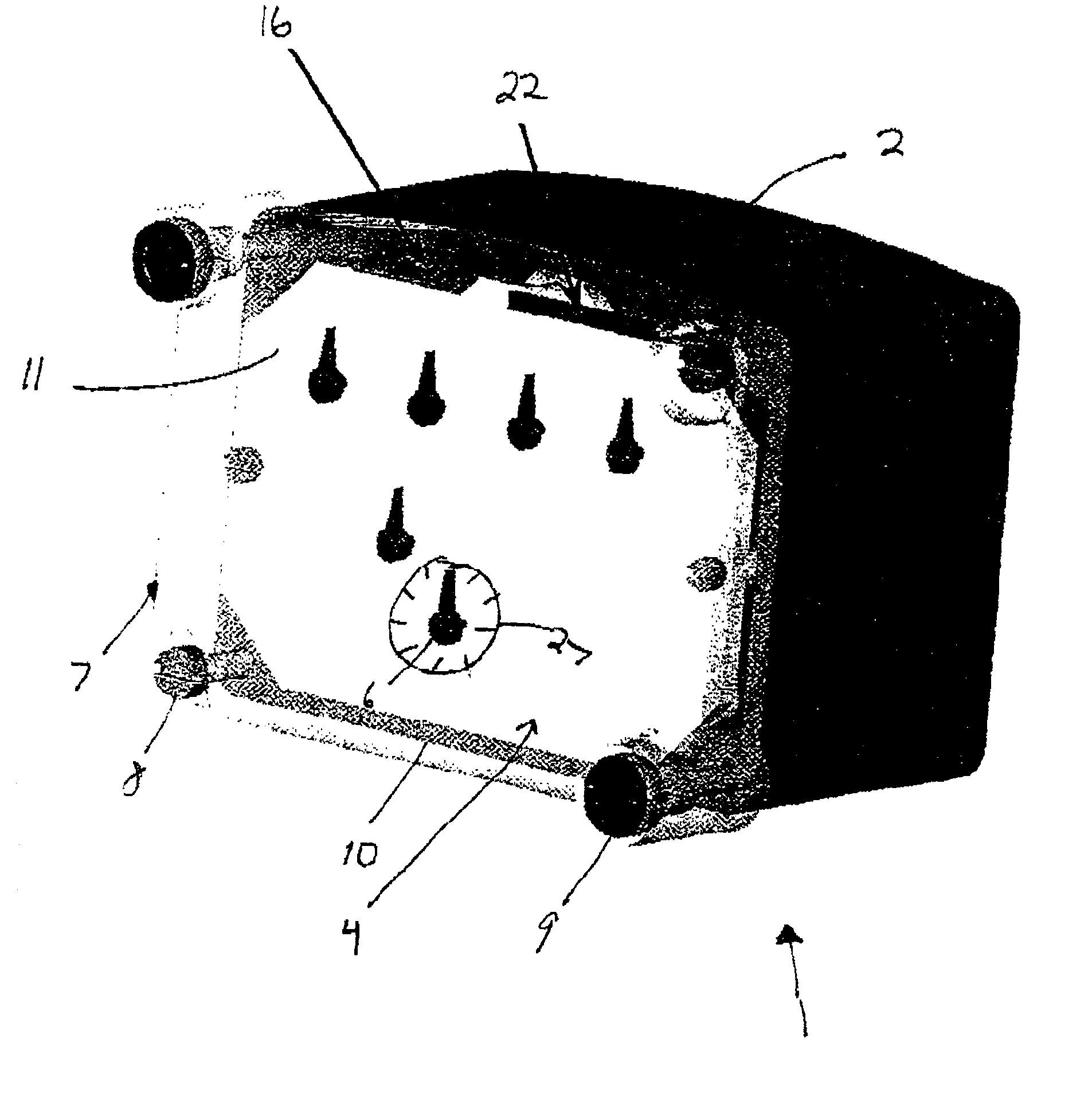
[0008]These and other needs are met by embodiments of the present invention, which provide an automatic meter reader module having an inner cavity of a given volume. The automatic reader meter module includes a printed circuit board (PCB) on which is mounted on-board circuitry and detection equipment configured to detect utility consumption metered by the utility meter. The module also includes a transmission device operatively coupled to the PCB that is configured to transmit data indicative of utility consumption. Further, the PCB is configured to mount entirely within the inner cavity of the utility meter without increasing the given volume of the cavity.

Problems solved by technology

The process was labor intensive and duplicative.
Moreover, unplanned nuisances such as dogs, inclement weather or a customer not being home (for inside meter sets) disrupted the meter reading process.
Although existing meters may be replaced with new meters that provide an automatic meter reading capability, such a replacement is uneconomical due to the large number of meters that need to be updated.
Equipment currently available for purposes of automatic meter reading can be quite costly to manufacture due in part to up-front tooling costs for molded plastic and stamped parts.
Some disadvantages of the described adapter lie in the initial tooling costs for the plastic parts that make up the adapter module and the positioning of the adapter module.
The additional tooling and parts substantially increase total installation cost to a utility, due to the large number of conventional meters still in service.
In some environments, the position of the meter will not accommodate an expanded housing, therefore, requiring replacement of the entire meter.
Externally mounting the automatic meter module or expanding the casing for installing the automatic meter module leaves the meter and module in a vulnerable state whereby metered gas usage may be altered.
That is, the conventional automatic meter module lessens the effectiveness of the tamper-resistant design.

Method used


Image

  • Automatic meter reading module
  • Automatic meter reading module
  • Automatic meter reading module

Examples


Embodiment Construction

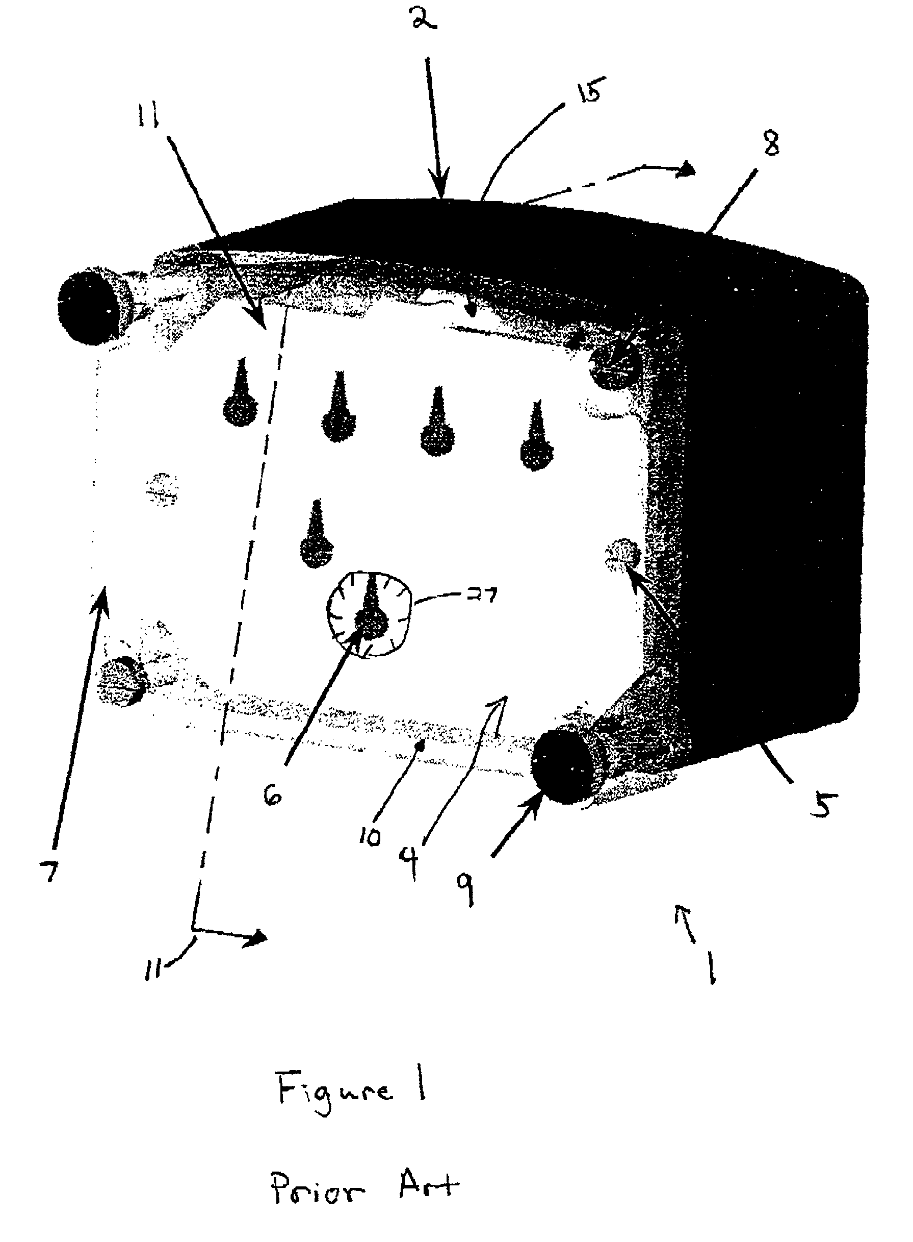
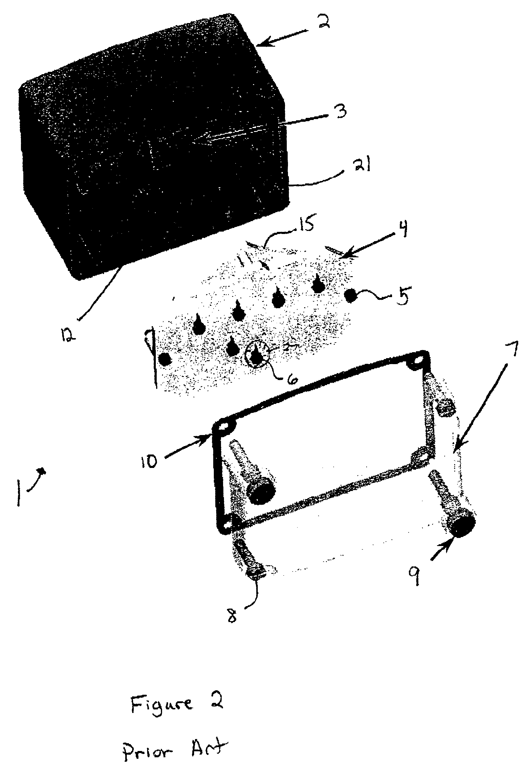
[0021]FIG. 1 depicts an existing mechanical utility gas meter 1 that contains a mechanical index display 4. The mechanical index 4 includes a display hand 6 each on one or more dials 27 that indicate gas consumption. Mechanical index mounting screws 5 secure the mechanical index 4 to the meter 1, which is protected by a clear index box 7. A gasket 10 arranged between the mechanical index 4 and the clear index box 7 further protects the meter 1 from environmental conditions external to the meter 1. Index box mounting screws 8 secure the clear index box 7 to the meter 1. Tamper evident seals 9 positioned over the head of the index box mounting screw 8 indicates any attempt to remove the clear index box 7. Display hands 6 display gas consumption, which is periodically read and recorded by meter reading personnel and further reported to generate a bill for the consumer. The problematic process of reading a meter 1 is labor intensive, repetitive, costly, and inviting to human error. To b...


PUM


Abstract

An automatic meter reader module is provided that is adapted to be retrofitted or installed in a new or existing utility meter. The module includes a printed circuit board (PCB) on which is mounted on-board circuitry and detection equipment configured to detect utility consumption metered by the utility meter. A transmission device operatively coupled to the PCB is configured to transmit data indicative of utility usage. The PCB is configured to mount within an inner cavity of the utility meter.

Description

RELATED APPLICATION[0001]This application claims priority from Provisional Application Ser. No. 60 / 288,056 filed on May 2, 2001 entitled: “AUTOMATIC METER READING MODULE”, the entire disclosure of which is hereby incorporated by reference herein.FIELD OF THE INVENTION[0002]The present invention relates to an automatic meter reading module, which when retrofitted to or installed in a utility meter, such as a gas meter, will enable the meter to support automated meter reading.BACKGROUND OF THE INVENTION[0003]Utility companies typically measure consumption using meters and bill their customers accordingly. Traditionally, at the end of a reporting period, a utility employee had physically read and recorded each customer's meter readout dials that reflected usage. The recorded data was eventually re-entered into an accounting system for billing purposes. The process was labor intensive and duplicative. Moreover, unplanned nuisances such as dogs, inclement weather or a customer not being ...

Claims


Application Information

Patent Timeline
IPC IPC(8): G08B23/00G01D4/00G01F15/06G01F15/075
CPCG01D4/008G01F15/063G01F15/0755Y02B90/24Y04S20/50Y04S20/30Y02B90/247Y02B90/20
Inventor FISCHER, JEFFREY L.
Owner SENSUS SPECTRUM LLC
Learn More