
Method for time synchronization of a computer network, and computer network with time synchronization

a computer network and time synchronization technology, applied in the field of time synchronization of a computer network, can solve problems such as deviation in timekeeping

Inactive Publication Date: 2005-12-27
SIEMENS AG
View PDF18 Cites 17 Cited by
  • Summary
  • Abstract
  • Description
  • Claims
  • Application Information

AI Technical Summary

Benefits of technology

[0015]In accordance with the concept of the present invention, the main computer, with the (N+2)-th interrupt, can again carry out time synchronization in accordance with the abovementioned method in order for secondary computers that were possibly non-synchronized during the first scan through the time synchronization to be synchronized via the renewed performance of the time synchronization. Moreover, after a certain period of time has elapsed, differences in running of the individual hardware clocks of the individual computers of the computer network can give rise to a relative deviation in the timekeeping of the individual computers, thereby necessitating renewed synchronization.
[0018]In this way, the main computer (in each cases without setting up any other particular connections to the secondary computers) can identify which secondary computers are in the synchronized state or in the non-synchronized state.
[0020]A further embodiment according to the present invention involves further main computers being provided in the computer network which, in turn, have a superordinate computer, at least with regard to the system time, and are synchronized with one another according to the abovementioned method. This makes it possible for even a relatively large computer network having, for example, a number of clusters, each including a main computer and a plurality of subordinate secondary computers, to be synchronized in such a way that the main computers are first synchronized with regard to their system time and then in turn the independently synchronize, in accordance with the abovementioned method—their assigned secondary computers.

Problems solved by technology

Moreover, after a certain period of time has elapsed, differences in running of the individual hardware clocks of the individual computers of the computer network can give rise to a relative deviation in the timekeeping of the individual computers, thereby necessitating renewed synchronization.

Method used


Image

  • Method for time synchronization of a computer network, and computer network with time synchronization
  • Method for time synchronization of a computer network, and computer network with time synchronization
  • Method for time synchronization of a computer network, and computer network with time synchronization

Examples


Embodiment Construction

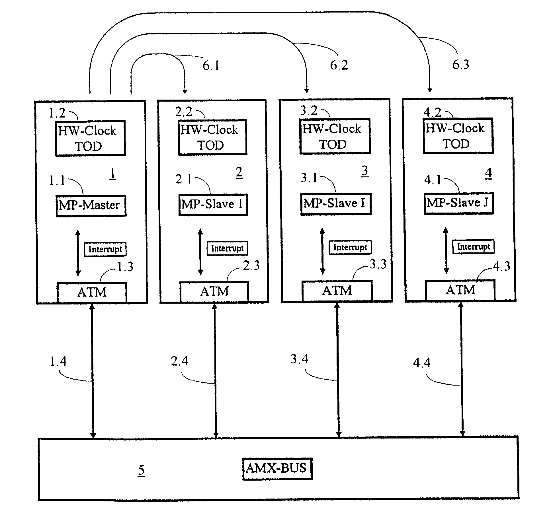
[0038]FIG. 1 shows a schematic illustration of a computer network having four computers 1 to 4 illustrated by way of example. The computer 1 represents the main computer (Master) 1, which is provided with a processor (MP-Master=Main Processor Master) 1.1, a crystal-controlled clock (HW-Clock=Hardware Clock) 1.2 and an interface 1.3 to an AMX bus 5 via the ATM connecting line 1.4.

[0039]Also shown are the secondary computers 2 to 3, which are each likewise equipped with a processor 2.1 to 4.1, a clock 2.2 to 4.2 and an ATM interface 2.3 to 4.3. The secondary computers 2 to 4 are also, in each case, connected to the AMX bus 5 via an ATM connecting line 2.4 to 4.4.

[0040]The connecting arrows 6.1 to 6.3 are intended to illustrate that the time synchronization to be carried out acts on the secondary computers 2 to 4 in a manner proceeding from the main computer 1.

[0041]FIG. 2 shows the time profile of the present invention's method for time synchronization, which can be carried out using ...


PUM


Abstract

A method for time synchronization of a computer network by a main computer, in which case, for synchronization with an N-th interrupt, a time signal corresponding to the instant of the interrupt plus a time interval between the interrupts is transmitted on an ATM bus and the secondary computers to be synchronized set their clock to this transmitted time signal with the next interrupt.

Description

BACKGROUND OF THE INVENTION[0001]1. Field of the Invention[0002]The present invention relates to a method for time synchronization of a computer network, preferably of a switching computer system, including at least one main computer (Master) with, in each case, at least one assigned secondary computer (slave), each computer being provided with at least one internal clock, and the computers being connected via at least one ATM bus (ATM=asynchronous transfer mode).[0003]Furthermore, the present invention relates to a computer network, preferably a switching computer system, including at least one main computer (Master) with, in each case, at least one assigned secondary computer (Slave), each computer being provided with at least one internal clock, and the computers being interconnected via at least one ATM bus.[0004]2. Description of the Prior Art[0005]At present there is no known prior art for real-time process computer systems, particularly switching computer systems, in which ti...

Claims


Application Information

Patent Timeline
Patent Type & Authority Patents(United States)
IPC IPC(8): H04J3/06H04L12/70H04Q11/04
CPCH04J3/0697H04Q11/0478H04J3/0664H04L2012/5613H04L2012/5674
Inventor EGGERS, HARALDSCHUCHT, JUERGENSTURM, RICHARD
Owner SIEMENS AG
Learn More