
Foot pad

a foot pad and foot technology, applied in the field of foot pads, can solve the problems of inability to provide a proper anti-skid effect or stability, small contact area ab>5/b>, etc., and achieve the effect of increasing the elasticity and the anti-skid effect of the foot pad

Inactive Publication Date: 2005-12-27
LITE ON TECH CORP
View PDF2 Cites 40 Cited by
  • Summary
  • Abstract
  • Description
  • Claims
  • Application Information

AI Technical Summary

Benefits of technology

The invention is a foot pad for electronic products that improves elasticity and anti-skid effect. It consists of an elastic conical body and at least one elastic rib that connects to the conical body. The conical body has a hollow portion that increases elasticity and contact area with the supporting surface, ensuring stability when using the electronic product. The conical body also has an outer conical surface with a root portion and an apex for better attachment to the electronic product. Overall, the foot pad provides better supporting effect and stability for electronic products.

Problems solved by technology

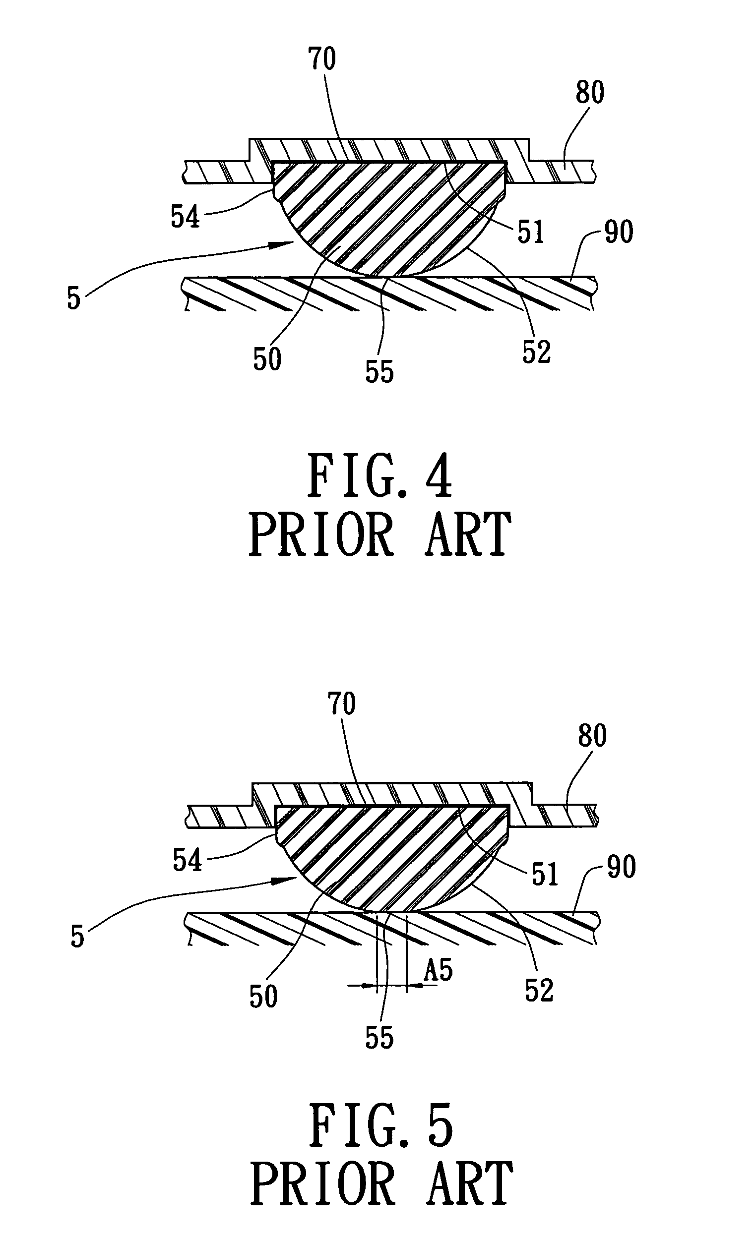
Therefore, the contact area A5 is small and cannot provide a proper anti-skid effect or stability when the electronic product 80 is used.

Method used


Image

  • Foot pad
  • Foot pad
  • Foot pad

Examples


first embodiment

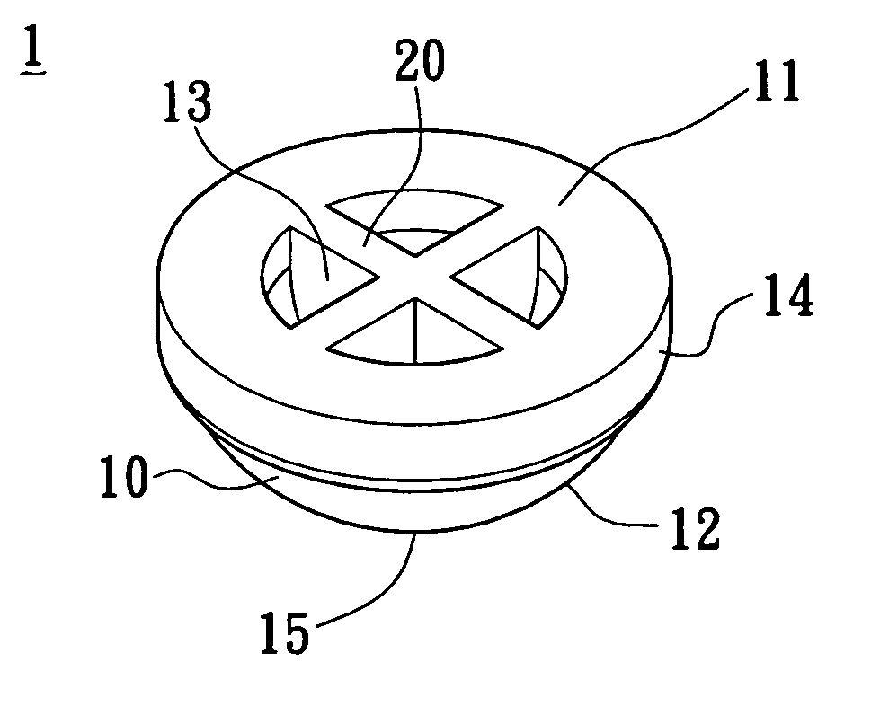
[0029]FIG. 6 to FIG. 8 illustrate the present invention. The present invention provides a foot pad 1. The foot pad 1 comprises an elastic conical body 10 and at least one elastic rib 20.

[0030]The elastic conical body 10 defines a connecting surface 11 and an outer conical surface 12. The connecting surface 11 defines a hollow portion 13 and the outer conical surface 12 has a root portion 14 connecting with an outer edge of the connecting surface 11. In this embodiment, the outer edge of the connecting surface 11 is a circle, but can also be an oval or other different shapes. A thickness t14 of the elastic conical body 10 at the root portion 14 of the outer conical surface 12 is larger than a thickness t15 of the elastic conical body 10 at an apex 15 of the outer conical surface 12.

[0031]Each of the elastic ribs 20 integrally connects to the elastic conical body 10 at a surface of the hollow portion 13. In this embodiment, the elastic ribs 20 are arranged perpendicular to each other....

second embodiment

[0035]FIG. 11 to FIG. 13 illustrate the present invention. Each of the elastic ribs 40 integrally connects to the elastic conical body 30 at a surface of the hollow portion 33. In this embodiment, the elastic ribs 40 are arranged in a parallel manner. The outer conical surface 32 of the elastic conical body 30 has an apex 35 for contacting an outer supporting surface (not shown). The outer conical surface 32 of the elastic conical body 30 has a root portion 34 connecting with an outer edge of the connecting surface 31. The thickness t34 of the elastic conical body 30 at the root portion 34 of the outer conical surface 32 is larger than a thickness t35 of the elastic conical body 30 at the apex 35 of the outer conical surface 32 and is larger than a thickness t40 of each of the elastic ribs 40. The elasticity of the foot pad 3 increases and the contact area is enlarged, so that the anti-skid effect is improved and the foot pad 3 is capable of absorbing the deformation of the electron...


PUM


Abstract

A foot pad has an elastic conical body and at least one elastic rib. The elastic conical body defines a connecting surface and an outer conical surface. The connecting surface defines a hollow portion, and the elastic rib integrally connects to the elastic conical body at a surface of the hollow portion. The outer conical surface has a root portion connecting with an outer edge of the connecting surface. A thickness of the elastic conical body at the root portion of the outer conical surface is greater than a thickness of the elastic conical body at other portions of the outer conical surface. Elasticity of the foot pad is thereby increased so as to enlarge a contact area contacting an outer supporting surface, so that an anti-skid effect is improved and the foot pad is capable of absorbing a deformation of an electronic product.

Description

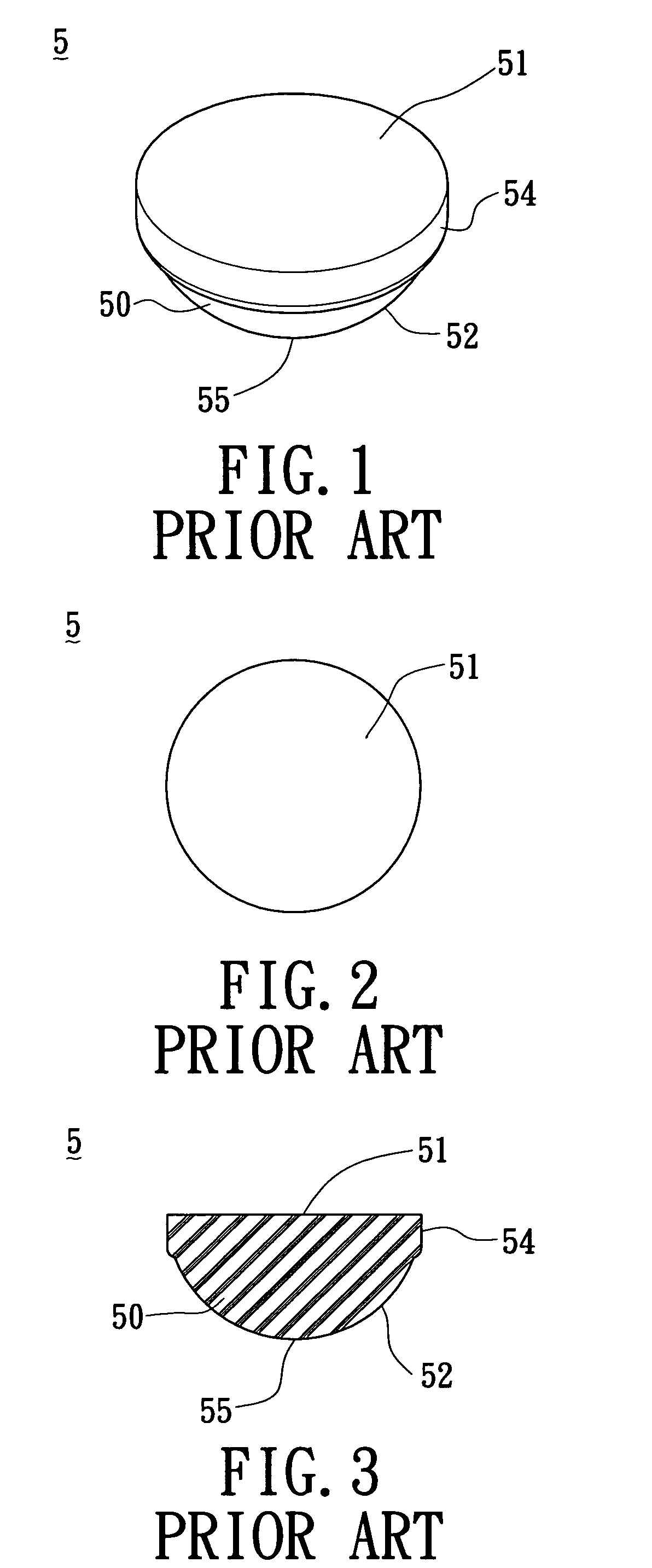
BACKGROUND OF THE INVENTION[0001]1. Field of the Invention[0002]The present invention relates to a foot pad, and more particularly, to a foot pad being affixed to a consumer electronic product.[0003]2. Background of the Invention[0004]It is a well known that consumer electronic products play an important role in the modem life. For example, desktops or scanners are commonly used in homes and offices. A consumer electronic product symmetrically fixes some foot pads on a bottom thereof to provide an anti-skid effect to ensure stability when the electronic product used on a desk.[0005]Referring to FIG. 1 to FIG. 3, a conventional foot pad 5 has an elastic conical body 50 made of natural rubber and having a solid structure. The elastic conical body 50 defines a connecting surface 51 and an outer conical surface 52. The outer conical surface 52 has a root portion 54 connecting with an outer edge of the connecting surface 51.[0006]Referring to FIG. 4, the connecting surface 51 of the elas...

Claims


Application Information

Patent Timeline
Patent Type & Authority Patents(United States)
IPC IPC(8): A47B91/04H01J15/00H02G3/08H05K5/02
CPCA47B91/04H05K5/0234
Inventor XIONG, ROGERHSUEH, CHI-REN
Owner LITE ON TECH CORP
Learn More