
Catheter introducer

Inactive Publication Date: 2005-12-27
LEMAITRE VASCULAR
View PDF8 Cites 75 Cited by
  • Summary
  • Abstract
  • Description
  • Claims
  • Application Information

AI Technical Summary

Benefits of technology

[0006]The present invention provides a catheter introducer device including a tapered tip which facilitates insertion of the catheter into the cystic duct.
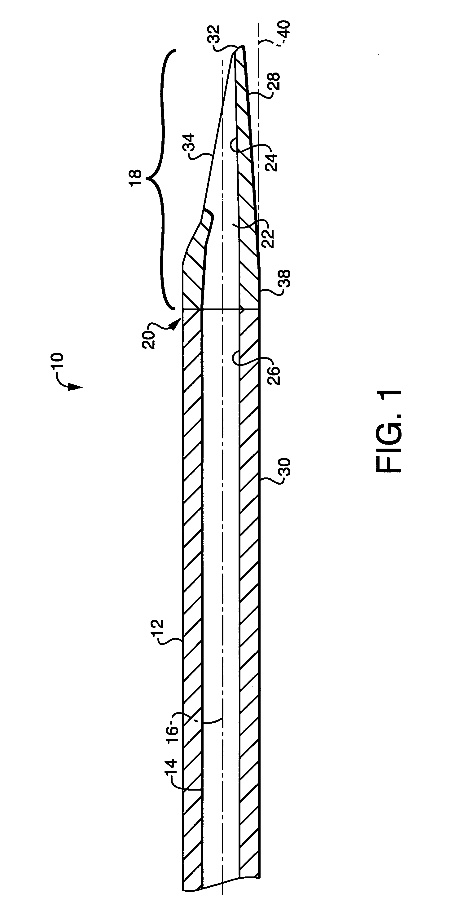
[0011]The head portion may be constructed within planes tangent to the outer surface of the tube. The smaller profile design of the head portion allows insertion of the head portion through the incision in the cystic duct, and placement within it. Following such insertion, a catheter may be inserted into the introducer from the proximal end, extended out from the head portion and guided into the lumen of the cystic duct. The curved design of the protrusion also provides good support for the catheter if it encounters resistance from valves or other obstructions.
[0012]The small profile design of the protrusion also makes it easier for the introducer to be inserted along the lumen of the cystic duct. During operation, electro-cauterization may be utilized to stop any bleeding at the incision site. This may cause the duct tissue to shrink, or a buildup of dead tissue to partially obstruct the lumen of the cystic duct. The leading edge of the tip can be used to pass through this narrowed incision, and then can be positioned for directing catheter insertion in the duct.
[0014]The interior surface may be curved along a radius of curvature. The radius of curvature may be a nonzero value or infinite. The channel may be concave along two axes. The exterior surface along the first portion of the head portion may completely surround the opening, thereby forming a protruding portion at the tip. The protruding portion may include a flat bill or a pointed tip. The head portion may remain within planes which are tangent to an outer surface of the tube. The channel may deflect the catheter from traveling along the longitudinal axis to a direction oblique to the longitudinal axis as the catheter is directed through the head portion. The head may be constructed such that the catheter exits the opening at an angle which is between zero and thirty degrees with respect to the longitudinal axis. The head portion may be constructed such that the longitudinal axis of the tube passes through the opening or such that the longitudinal axis of the tube intersects the channel. A line connecting the first portion of the exterior surface at the opening and the tip may lie in a plane which is oblique with respect to the longitudinal axis.

Problems solved by technology

The elasticity of the duct wall makes such a procedure very difficult.
The curved introducers represent an improvement over the straight introducers, but still do not provide the support and control necessary for optimized catheter insertion.
In general, both straight and curved introducers share a common problem.
Laparoscopic procedures are difficult to execute because the surgeon is operating with instruments on an extended lever arm.
While existing introducers may enable the surgeon to navigate the end of the catheter proximate the incision, they still require that the surgeon enter the incision with the end of the catheter, which can be difficult, given the necessary flexibility of the catheter, the diameter of the catheter and the typical dimensions of the incision.

Method used


Image

  • Catheter introducer
  • Catheter introducer
  • Catheter introducer

Examples


embodiment 44

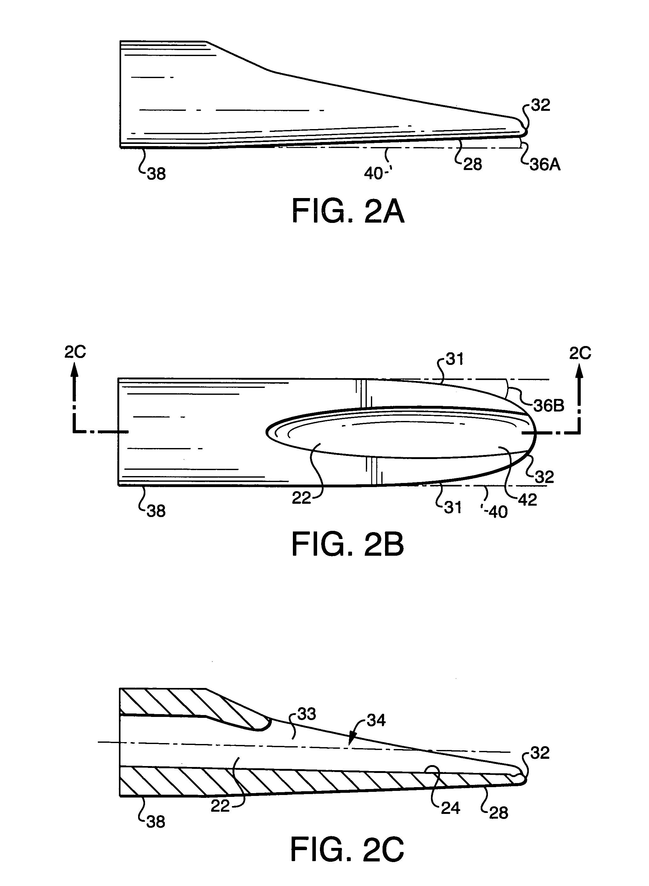
[0037]As shown in FIGS. 2A–2C, this embodiment includes a channel 42 formed between the lower interior surface 24 which extends from the proximal end 38 of the head portion 18 to the tip 32 and interior sidewalls 33 and which, by the nature of the interior surface of the lumen, is concave around the longitudinal axis. The catheter rides within this channel as it is directed out of the opening 34 and through the duct. FIGS. 3A–3C show another embodiment 44 of the straight head portion 18. This embodiment is similar to that shown in FIGS. 2A–2C, with the exception that the channel 22 terminates at a lip 46a of the tip 32. In this embodiment, lip 46a is formed to be continuous with exterior portion 48 of the head portion.

[0038]Shown in FIGS. 4–7 are various configurations of the lip 46. Each configuration is advantageous in enabling the surgeon to insert the tip and head portion into the incision in the cystic duct and through the valves and other obstructions in the duct that may be e...

embodiment 60

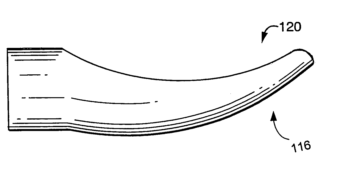
[0039]In another embodiment of the present invention, the head portion may be curved with respect to the longitudinal axis to enable the interior surface of the head portion to impart a deflecting force on the catheter as it is directed through the head portion and beyond the opening therein. FIGS. 8A–8D show such an embodiment 60, wherein FIG. 8A is a side view of the head portion 60, FIG. 8B is a top view of the head portion, FIG. 8C is a cross-sectional view of the head portion 60, taken along line 8C—8C in FIG. 8B and FIG. 8D is a three-dimensional perspective view of the head portion 60. As shown in FIGS. 8A–8D, head portion 60 is generally spoon-shaped, wherein interior surface 62 and the exterior surface 64 are curved upwardly with respect to the longitudinal axis 16. The combination with sidewalls 66 and interior surface 62 result in a channel 68 that is concave in two-dimension, both along the longitudinal axis 16 and around it. This feature is particularly shown in FIG. 8D...

embodiment 90

[0043]In yet another embodiment of the present invention, the head portion may be curved with respect to the longitudinal axis to enable the interior surface of the head portion to impart a deflecting force on the catheter as it is directed through the head portion and beyond the opening therein, however, with shallower side walls and a lower profile than the spoon-shaped head portion described above. FIGS. 12A–12D show such an embodiment 90, wherein FIG. 12A is a side view of the head portion 90, FIG. 12B is a top view of the head portion 90, FIG. 12C is a cross-sectional view of the head portion 90, taken along line 12C—12C in FIG. 12B and FIGS. 12D and 12E are three-dimensional perspective views of the head portion 90. As shown in FIGS. 12A–12E, head portion 90 is generally scoop-shaped, wherein interior surface 92 and the exterior surface 94 are curved upwardly with respect to the longitudinal axis 16. The combination of shallow sidewalls 96 and interior surface 92 result in a c...


PUM


Abstract

A catheter introducer includes a tube having a proximal end, a distal end and a lumen extending therethrough along a longitudinal axis of the tube for accommodating a catheter traveling along a longitudinal axis of the tube and a head portion coupled to the distal end of the tube. The head portion includes an aperture in fluid communication with the lumen at a proximal end thereof and a tip at a distal end thereof, an exterior surface extending from the proximal end thereof to an opening of the head portion along a first portion of the head portion and extending from the proximal end thereof to the tip along an opposing portion of the head portion and an interior surface extending from the aperture to the opening of the head portion along the first portion of the head portion and extending from the aperture toward the tip along the opposing portion of the head portion. The exterior surface circumferentially tapers from the proximal end to the distal end and the interior surface forms a channel for receiving a catheter passing through the lumen and the aperture, the channel being concave along at least one axis.

Description

FIELD OF THE INVENTION[0001]The invention relates generally to medical devices and more particularly to catheter introducing devices.BACKGROUND OF THE INVENTION[0002]During surgical procedures, catheter introducers are often used to provide a conduit for passage of catheters and other relatively long, thin and flexible medical devices, for example, guide wires, into lumens in a patient. For example, in cholangiography procedures, an introducer is used to establish a guide channel to permit advancement of a catheter to an incision in the wall of the cystic duct of the gallbladder. The catheter is introduced through the introducer, under control of the surgeon, and is extended out of the introducer. The distal tip of the catheter is manipulated by the surgeon into the incision in the cystic duct, and navigated by the surgeon through the lumen of the cystic duct forward and through the valve of Heister. During this procedure, the valves or other obstructions can inhibit the catheter's ...

Claims


Application Information

Patent Timeline
IPC IPC(8): A61M25/00A61M25/06
CPCA61M25/0068A61M25/0069A61M25/0662
Inventor MCDONALD, DAVIDWILLY, CHRISTINE
Owner LEMAITRE VASCULAR
Learn More