
Force feedback and texture simulating interface device

Inactive Publication Date: 2005-12-27
IMMERSION CORPORATION
View PDF131 Cites 132 Cited by
  • Summary
  • Abstract
  • Description
  • Claims
  • Application Information

AI Technical Summary

Benefits of technology

[0014]Yet another object of the invention is a man-machine interface comprised of a glove capable of sensing finger and hand positions and hand orientation, which may exert, measure and dynamically vary and control the forces applied to each finger, and which may vary the tactile array pattern presented to each finger tip, and which may vary the pressure applied to a portion of the hand, and which may vary the temperature applied to a portion of the hand.
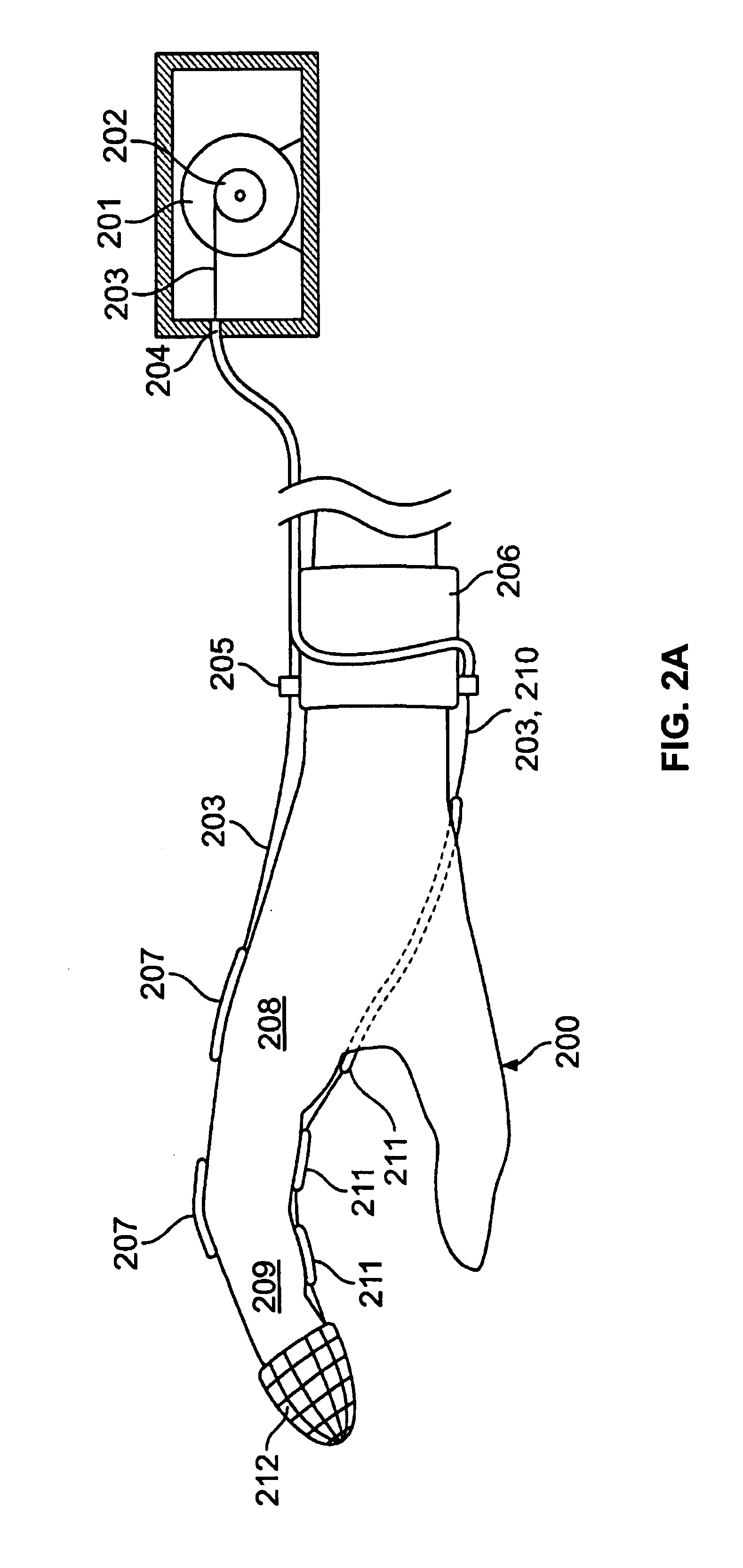
[0036]As tension is increased, tendons which pass along the back side of a finger press against the joints and do not tend to pull the glove material away form the hand or fingers. The tension of the tendon restricts the joints over which the tendon passes from flexing in a direction which attempts to extend the tendon further.

Problems solved by technology

Although generating a graphic representation of an environment may be time consuming and non-trivial to implement, much of the theory has been explored and is well-understood by those skilled in the art of interactive 3-D computer graphics and solid modeling.
The main drawback of these computer input devices is that they don't permit human users to enter information in a manner which may be the most efficient and natural.
This whole procedure seems very awkward and unintuitive when compared to what a person would normally do when confronted with a similar task in the “real world,” i.e., he would simply reach out, pick up and rotate the object!
However, lack of force feedback to the glove wearer has reduced the effectiveness of these open-loop manipulation approaches.
Without some kind of grasping force and tactile feedback, this task would be extremely difficult.
It may be frustrating and time consuming for the user to learn one of these “unnatural” methods of grasping an object, and the sensation of interacting in a virtual environment will be reduced.

Method used


Image

  • Force feedback and texture simulating interface device
  • Force feedback and texture simulating interface device
  • Force feedback and texture simulating interface device

Examples


Embodiment Construction

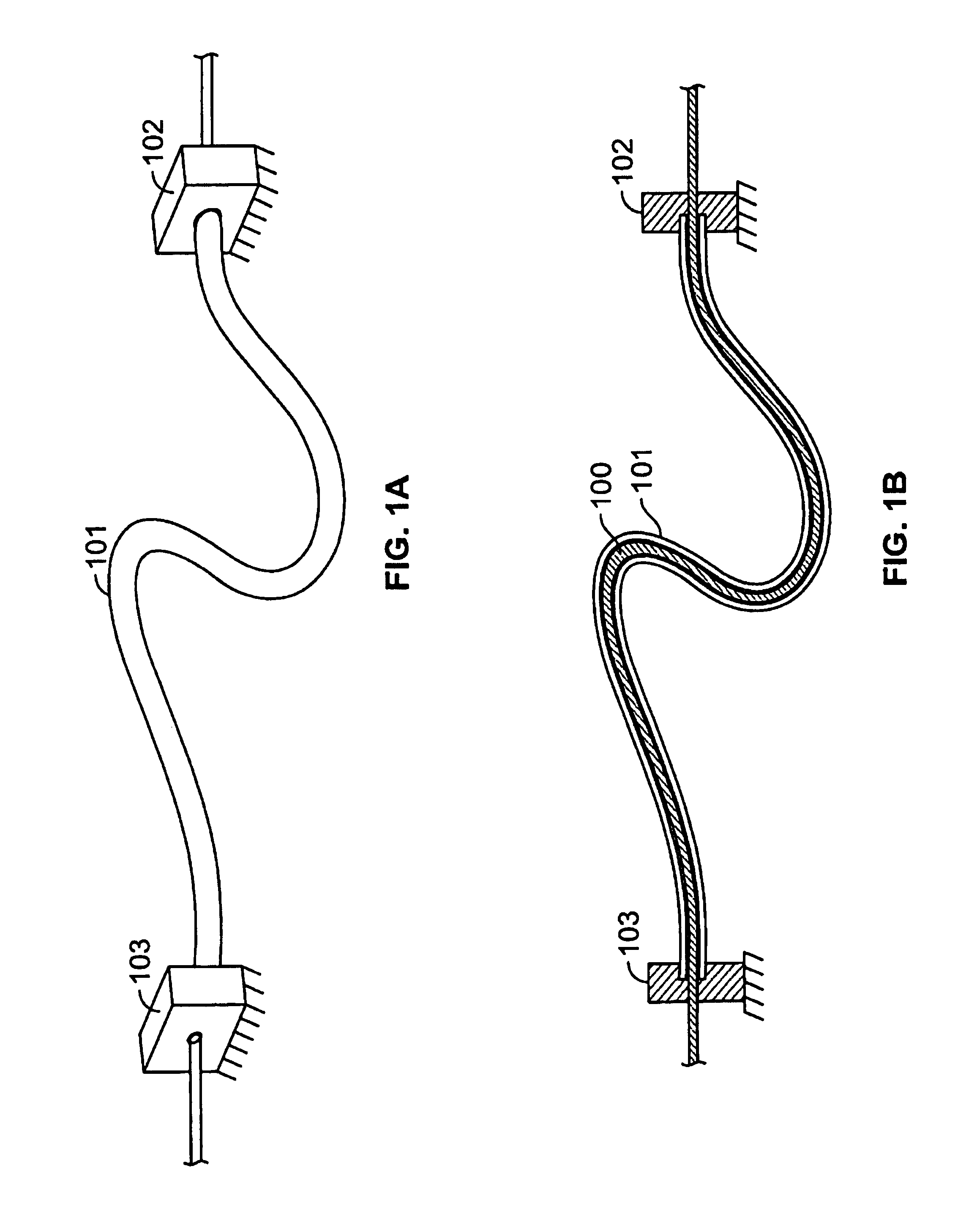
[0074]FIGS. 1a and 1b show how the force generated by a force actuator may be transmitted to a chosen location. More specifically, FIG. 1a shows a perspective view of a tendon assembly, and FIG. 1b shows a cross-section view. The tendon assembly is comprised of a low friction, high modulus of elasticity and high tensile strength, flexible tendon cable 100 (e.g., Dacron™ 20 lb. test fishing line or Kevlar™ thread) inside an assembly employing one or more concentric flexible, low-compressibility tubular casings 101 (e.g, Teflon™ tubing). One end 102 of the casing assembly is secured near the force actuator and the other end 103 of the casing is secured near the location where the force is to be applied (e.g., for a feedback glove, the casing may be secured to the wristband, and the force applied to the finger tip). By using a plurality of concentric casings (e.g., a #20 Teflon tube inside a #14 tube) rather than simply increasing the thickness of the wall of a single casing, the resul...


PUM


Abstract

A man-machine interface is disclosed which provides force, texture, pressure and temperature information to sensing body parts. The interface is comprised of a force-generating device (900) that produces a force which is transmitted to a force-applying device (902) via force-transmitting means (908). The force-applying device applies the generated force to a sensing body part. A force sensor (909) associated with the force-applying device measures the actual force applied to the sensing body part, while angle sensors (917) measure the angles of relevant joint body parts. A computing device (911) uses the joint body part position information to determine a desired force value to be applied to the sensing body part. The computing device combines the joint body part position information with the force sensor information to calculate the force command which is sent to the force-generating device. In this manner, the computing device may control the actual force applied to a sensing body part to a desired force which depends upon the positions of related body parts. In addition, the interface is comprised of a displacement-generating device (901) which produces a displacement which is transmitted to a displacement-applying device (902) (e.g., a texture simulator) via displacement-generating means (920). The displacement-applying device applies the generated displacement to a sensing body part. The force-applying device and displacement-applying device may be combined to simultaneously provide force and displacement information to a sensing body part. Furthermore, pressure and temperature-applying devices may be combined to also provide pressure and temperature sensations to a sensing body part. In addition, a force-applying device may be attached to a sensing body part and apply force to the sensing body part, where the force is applied relative to a reference location not rigidly affixed to the living body.

Description

[0001]This application is a continuation of application Ser. No. 08 / 858,737 filed May 19, 1997, U.S. Pat. No. 6,059,506, which is a continuation application Ser. No. 08 / 373,531 filed Jan. 7, 1995, U.S. Pat. No. 5,631,861, which was a continuation of Ser. No. 07 / 929,895 filed Aug. 10, 1992, abandoned, which was a continuation-in-part of Ser. No. 07 / 474,168 filed Feb. 2, 1990, U.S. Pat. No. 5,184,319.TECHNICAL FIELD[0002]This invention relates to a man-machine interface and in particular to an interface that measures body part positions and provides force, texture, pressure and temperature feedback to a user.BACKGROUND OF THE INVENTION[0003]A new manner of computer interaction is now in its infancy. The words “virtual environment” or “virtual reality” will soon be commonplace. A virtual environment is an environment where some portion of the environment is artificially simulated, most often via a computer. A computer may create a graphic simulation of an environment, complete with gra...

Claims


Application Information

Patent Timeline
IPC IPC(8): G06F3/00G06F3/01
CPCB25J13/02G06F3/011G06F3/014G06F3/016B25J13/025
Inventor KRAMER, JAMES F.
Owner IMMERSION CORPORATION
Learn More