
Torsion absorber for roller crank assemblies

a technology of roller crank and absorber, which is applied in the direction of roofs, manufacturing tools, transportation and packaging, etc., can solve the problems of tarp being tight in the area, loose everywhere else, and not being very successful, so as to achieve the effect of keeping tension and being convenient to us

Inactive Publication Date: 2005-12-27
HONEY POINT COMPANY
View PDF17 Cites 29 Cited by
  • Summary
  • Abstract
  • Description
  • Claims
  • Application Information

AI Technical Summary

Benefits of technology

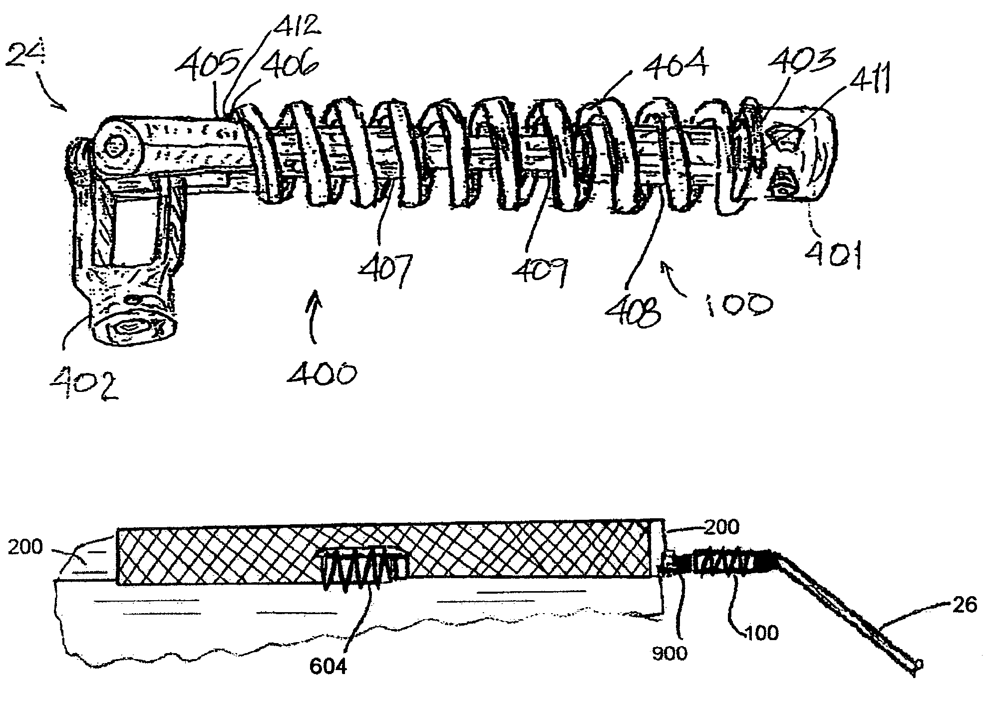
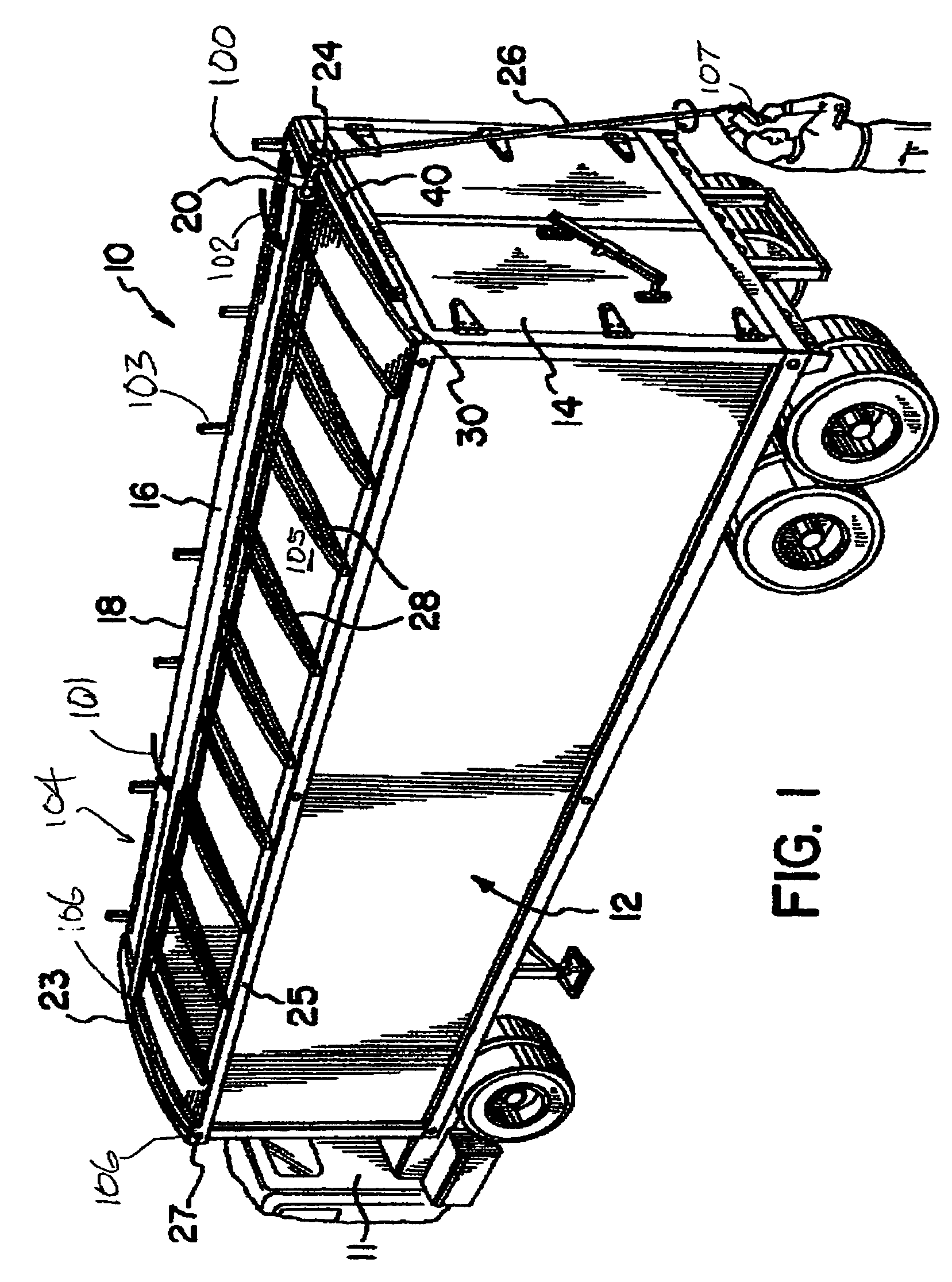
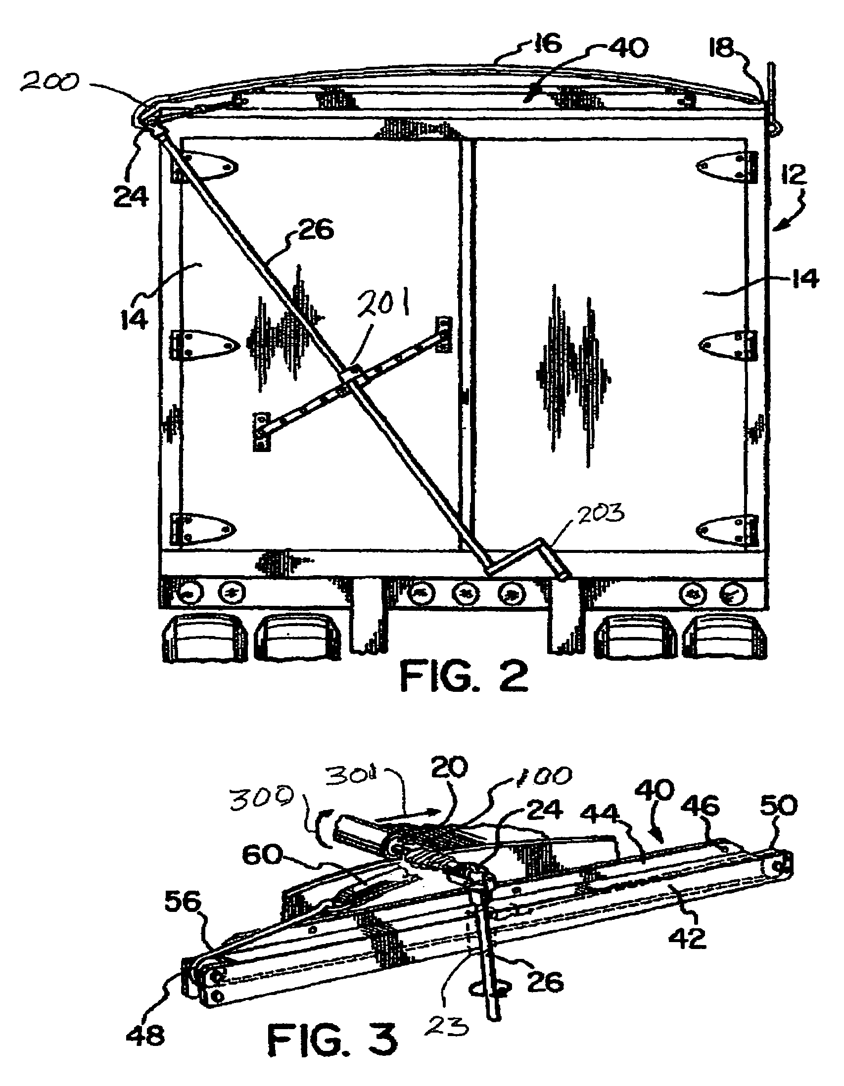
[0012]In a first exemplary embodiment, a limited rotation torsion spring is placed between the roll bar and crank handle of a roll-tarp system to allow controlled stressing of the roll bar to accommodate occasional overheight loads and help to keep tension on the tarp to keep the tarp tight and help keep the roll bar latched even if the load settles. This torsion spring or torsion absorber has applicability to a wide variety of roll bar cranking assemblies, both manual and motorized, especially those using U-joint connections. The crank handle can be weighted and padded to make it easier to use and safer.

Problems solved by technology

When large or uneven loads are present such that the top of the load is higher than the bows, which is a clear misuse of the tarp system, the tarp must pass over a longer distance in covering the “over-bow” portion of the load relative to the remainder of the container and this can result in the tarp being tight in the area over-bow but loose everywhere else unless the roll tube is excessively stressed by over-twisting the crank and applying a huge torque to the roll tube to pull very hard on the tarp to try to stretch the tarp sufficiently to put the roll tube into a proper latched position under a latch plate on an upper side edge of the trailer.
This is a risky action, which operators should recognize as being risky, but since truckers are often paid by the load or weight, when they have bulky materials or light materials there is a strong financial incentive to try to maximize the load even to the extent of temporary unsafe conditions.
This can cause all kinds of problems, but since truckers are paid by load or weight, they may nevertheless feel compelled by financial considerations to have loads that extend over the bows in some portion of the container.
To maximize the load, the trucker may start with an overbow load and think that by rocking the trailer forward and back (by accelerating and braking or jerking the clutch) to try to jerk the load into even distribution, but that is not usually very successful, especially if the load is sticky.
Even if successful, that jerking obviously adds wear and tear on drive trains, transmissions, brakes and tires.
However, that risky maneuver raises the possibility of slip and fall injury to the trucker during this climbing, balancing, and shoveling, particularly if the weather is icy, snowy, or rainy, or if the load is wet and slippery.
This overstressing requires tremendous torque because tarps do not stretch easily.
An over-bow load might take 200 pounds or more of force on the crank handle to rotate the roll tube sufficiently to latch for a sufficient distance that the trucker feels it probably won't come loose during travel, and even then there is likely to be a portion of the roll bar not fully latched.
Unless the trucker weighs well over 200 pounds, that force may be sufficient to lift the trucker off the ground, which is obviously undesirable.
If the crank handle is slippery, any slip under that kind of pressure may result in the handle slipping out of the operator's hand and then being whipped around viciously with possible injury to the operator or others nearby.
Also, since the crank arm might typically be 10 feet long, 2000 foot pounds or more of torsional force might actually be put on the U-joint and roll tube by this over-bow tarp tightening action, and this can lead to damage or even breaking of the roll tube or crank or U-joint, with consequent risk to everyone around, including adjacent vehicles, but especially to the operator himself.
If the roll bar breaks, it may break several feet forward of the back of the truck, and this requires repair and welding of a new end on the roll bar at significant expense and significant delay to the trucker and with resultant delay in delivery of the load.
If the roll bar does not break, it will still be in the overstressed state and is also now “cocked” so that if an unsuspecting person unlatches the crank to roll up the tarp to uncover the load, there could be an undesirable whipping action of the crank as it seeks to rotate to relieve 2000 foot pounds or more of stress.
This accentuates the risk of the crank slipping and popping back at the operator.
Another problem created by oversize loads is that if the load settles, the stretched tarp may become loose enough to flap in the wind like a flapping sail, increasing wear on the tarp and shortening its useful life.
If the loads settles sufficiently, the tarp might even come unlatched and act like a giant spinnaker or parachute, pulling the crank handle and mount right off the back or side of the trailer and flipping it around with possible damage to adjacent vehicles.
Motorized tarp covers may allow simpler tightening of loose roll bars but such tightening is not generally automatic and requires the operator to notice the need for tightening and then to activate the motorized crank.
Loose parts could pose a hazard to other motorists.

Method used


Image

  • Torsion absorber for roller crank assemblies
  • Torsion absorber for roller crank assemblies
  • Torsion absorber for roller crank assemblies

Examples


Embodiment Construction

[0040]Referring now to the drawings, and initially to FIGS. 1 and 2, an 18-wheeler truck trailer rig 10 includes as principal components a truck cab 11 and an open top container trailer 12. Truck cab 11 would have 8 rear wheels, but only 2 are shown. The container 12 is particularly suitable for hauling grain, earth, refuse, or the like, which generally is loaded into the container 12 through the open top. Generally material is removed from the container 12 through the top (for example by a suction hose), a trap door in the floor (not shown), or rear doors 14 (for example by a hydraulic lift (not shown) either in rig 12 or in a dumping station (not shown). A similar trailer construction is shown in U.S. Pat. No. Re. 31,746, the disclosure of which is incorporated in its entirety by reference herein to the extent not in conflict with anything here.

[0041]The exemplary container 12 is provided with a cover system 104 to protect the contents from the elements such as rain, sleet, snow o...


PUM


Abstract

A resilient torque absorber is placed between a roll bar and a U-joint of roll bar mechanism such as that used in roll-tarp covers for truck trailers. The absorber allows more precise adjustment of tightness and helps prevent accidents caused by over-tightening of tarps or by tarps loosening during load settling.

Description

CROSS REFERENCE TO RELATED APPLICATIONS (if applicable)[0001]This application is based on copending U.S. provisional patent applications no. 60 / 356,288 filed Feb. 12, 2002 and no. 60 / 372,580 filed Apr. 13, 2002.NOT FEDERALLY SPONSORED RESEARCH & DEVELOPMENT[0002]This invention was not Federally sponsored or funded.BACKGROUND OF THE INVENTION[0003]The invention relates to roll-tarp systems and to crank assemblies such as, for example, those classed in class 296, subclasses 98–100.[0004]Various types of truck, trailer and container bodies are designed to be loaded through an open top. Such bodies are typically used to haul grain, earth or refuse. It is desirable to use tarpaulins or other coverings to close the open tops of such containers. The tarpaulins serve to shelter the contents of trucks, trailers or containers against the elements and to maintain the contents in the containers when the containers are exposed to high winds or moved from place to place.[0005]Several systems are ...

Claims


Application Information

Patent Timeline
IPC IPC(8): B25B13/48B60J7/08
CPCB25B13/48B25B13/481B60J7/085
Inventor LEISCHNER, HENRY G.CAGLE, PATRICK R.
Owner HONEY POINT COMPANY
Learn More