
Communication cable

a communication cable and cable technology, applied in the field of communication cables, can solve the problems of incorrect control signals being supplied, interference of electrical signals over these electrical wires, and electromagnetic interference (emi) or radio frequency interference (rfi)

Inactive Publication Date: 2005-12-13
RICKENBACH ROBERT
View PDF22 Cites 133 Cited by
  • Summary
  • Abstract
  • Description
  • Claims
  • Application Information

AI Technical Summary

Benefits of technology

[0020]A fourth basic embodiment of the present invention is directed to a method of communicating between a computer and a machine comprising the step of installing b

Problems solved by technology

Each of these machines produce electromagnetic interference (EMI) or radio frequency interference (RFI).
The transmission of the electrical signals over these electrical wires can be interfered with by the EMI, RFI, ground loops and or ground currents.
This interference can result in incorrect control signals being supplied from the machine to the computer or vice versa.
In the past, this problem, though relatively common, has been just lived with as there has not been any known structure that has been available to correct the problem.
However, in the past, fiberoptic cables were relatively mechanically sensitive and frequently installations could be somewhat abusive.
The result was the fiberoptic cable broke or deteriorated to where it was inoperative.

Method used


Image

  • Communication cable
  • Communication cable
  • Communication cable

Examples


Embodiment Construction

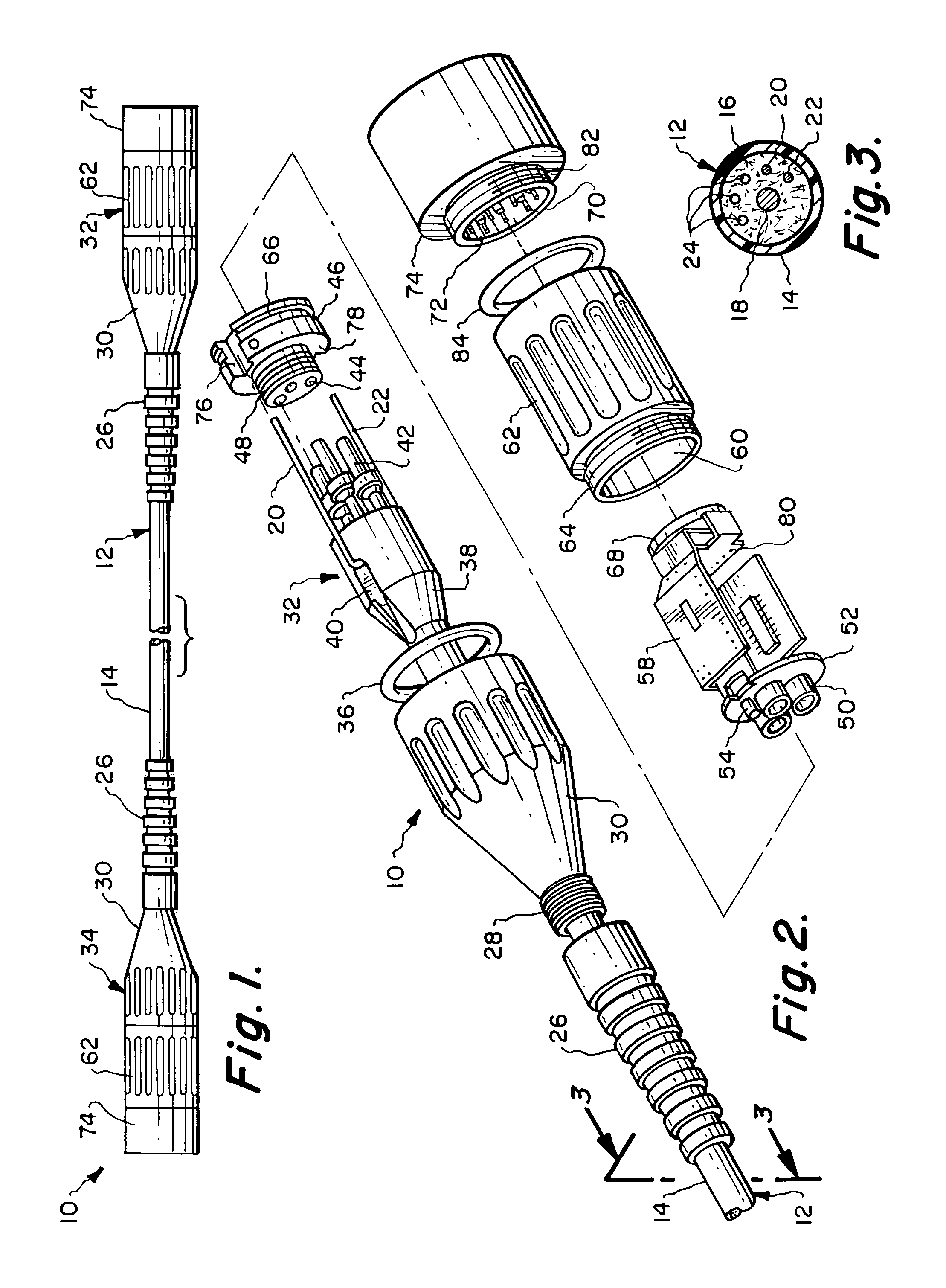
[0028]Referring particularly to the drawings, there is shown in FIGS. 1–3 the communication cable 10 of this invention. Communication cable 10 is formed of an elongated flexible conductor 12 which can be any desired length, normally from a few feet to thirty, forty, fifty feet or more in length. The conductor 12 is basically cylindrical, however any desired shape could be utilized. Conductor 12 is formed of an outer cover 14 which is in the shape of a tube which has an internal chamber 16. The cover 14 will normally be constructed of a plastic, rubber or other similar type of insulating material.

[0029]Centrally located within the internal chamber 16 is a strength member 18. The strength member 18 will normally be constructed of any material that has a high tensile strength. Typical desirable materials would be steel, carbon fiber or a material that is sold under the trademark of Kevlar. Whatever material that is selected for the strength member 18, it is the primary requirement that...


PUM


Abstract

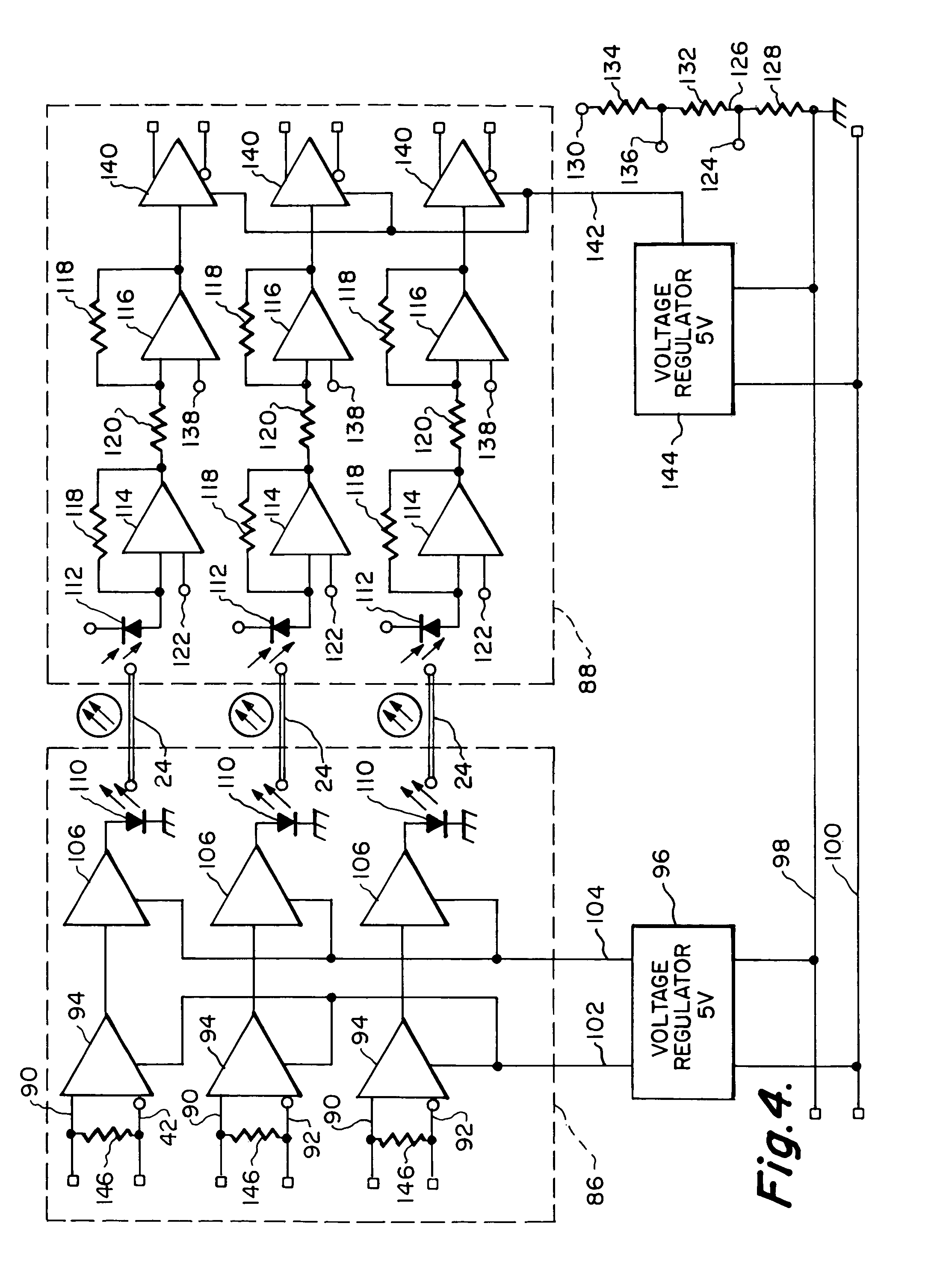
A communication cable which takes the form of an elongated flexible conductor which has mounted at one end thereof a transmitting connector and at the opposite end thereof a receiving connector. The conductor has integratingly mounted therein a plurality of optical fibers and a plurality of electrical wires. The transmitting connector includes a light emitting device for each optical fiber and a flexible printed circuit board holding electronic circuitry for converting electrical signals into optical signals. Further, the transmitting connector has an electrical interface accessible by the user. The receiving connector includes a photodetector for each optical fiber and also a flexible printed circuit board holding electronic circuitry for converting optical signals back to electrical signals. The receiving connector also has an electrical interface accessible by the user.

Description

BACKGROUND OF THE INVENTION[0001]1. Field of the Invention[0002]This invention relates to a communication cable and more specifically to a communication cable which is constructed to include both electrical wires and optical fibers.[0003]2. Description of the Related Art[0004]In the operation of machines that are computer controlled, there is required a communication cable. The communication cable would extend between the machine and the computer. Typical machines or pieces of equipment would be metal forming machines or any machine whose operation is controlled by computer.[0005]It is common that the computer is spaced some distance from the machine. To connect the machine to the computer a cable is required. Normally, in a place of business, there will be several machines. Each of these machines produce electromagnetic interference (EMI) or radio frequency interference (RFI). There also can be produced ground loops and ground currents. The typical cable that interconnects the mach...

Claims


Application Information

Patent Timeline
IPC IPC(8): G02B6/36G02B6/38
CPCG02B6/3817G02B6/3878
Inventor RICKENBACH, ROBERT
Owner RICKENBACH ROBERT
Learn More