
Compaction quality assurance based upon quantifying compactor interaction with base material

a compactor and compactor technology, applied in the direction of specific gravity measurement, instruments, roads, etc., can solve the problems of incomplete quality assurance test at one location, inability to quantify the interaction between compactor and base material, and inability to accurately determine the quality of compaction

Inactive Publication Date: 2005-12-13
CATERPILLAR INC
View PDF8 Cites 57 Cited by
  • Summary
  • Abstract
  • Description
  • Claims
  • Application Information

AI Technical Summary

Benefits of technology

The patent describes a method and device for compacting a base material using a compactor. The compactor moves over the base material and quantifies the interaction between it and the material to gather quality control compaction data. This data is used to determine compaction quality assurance data. The device includes a roller and an electronic data processor with algorithms for quantifying sinkage deformation and ensuring quality control during compaction. The technical effect of this patent is to provide a more efficient and accurate method for compacting base materials.

Problems solved by technology

If the prescribed truck at the prescribed speed produces ruts greater than the prescribed depth, then the base material compaction is deemed unsatisfactory and must be further compacted before further construction on the base material can be approved.
While most of the these quality assurance techniques have proven over time to be valid means by which the compaction quality of a base material can be assured, there are drawbacks to this method of progressing through a construction project.
Since the level of compaction can vary substantially over an area to be compacted, a quality assurance test at one location can be completely inaccurate with regard to another location some distance away from the tested area.
Thus, inadequate compaction in one area can, and sometimes does, go undetected after a quality assurance test at another location on the base material suggests that an entire area has been satisfactorily compacted.
Another drawback in current construction processes involves the costs of waiting for a quality assurance test to be initiated and performed after completion of the compaction process.
In other words, the down time involved in waiting to proceed to a next stage of construction after completion of a compaction process can increase inefficiencies and substantially increase the overall costs of a construction project.
In addition, if the quality assurance test indicates a failure to meet compaction specifications, further delays can occur in determining what, and how extensive a rework will be required to correct for the failure(s).
While this compaction monitoring technique can improve a operator's confidence that the base material will pass a compaction quality assurance test, the technique does nothing for the costs associated with waiting for the compaction quality assurance test to occur and be completed.
Nevertheless, this system could have promise, but does suffer from the drawback of reliance upon referencing an off-board elevational reference (GPS Satellite or Elevation Bench Mark) in order to perform as described.
In other known strategies, a density measuring device may be attached to a compactor, but accurate use of the device requires that the compactor remain stationary for some substantial period of time.
Unfortunately, this system is also strongly dependent on accurate assumption inputs to its algorithm(s).
Still, none of these strategies are useful in reducing downtime associated with waiting for a compaction quality assurance test to be performed and completed.

Method used


Image

  • Compaction quality assurance based upon quantifying compactor interaction with base material
  • Compaction quality assurance based upon quantifying compactor interaction with base material
  • Compaction quality assurance based upon quantifying compactor interaction with base material

Examples


Embodiment Construction

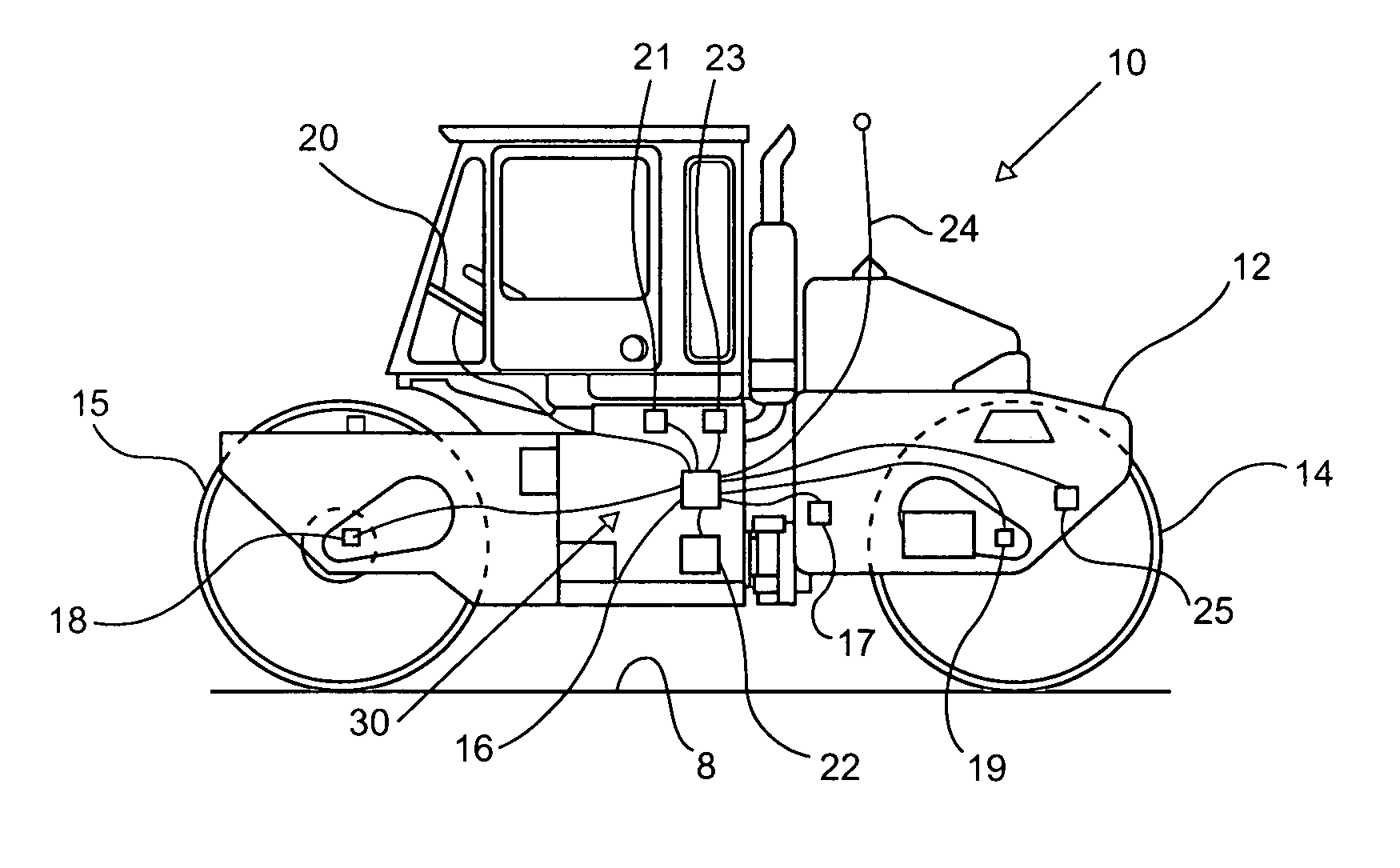
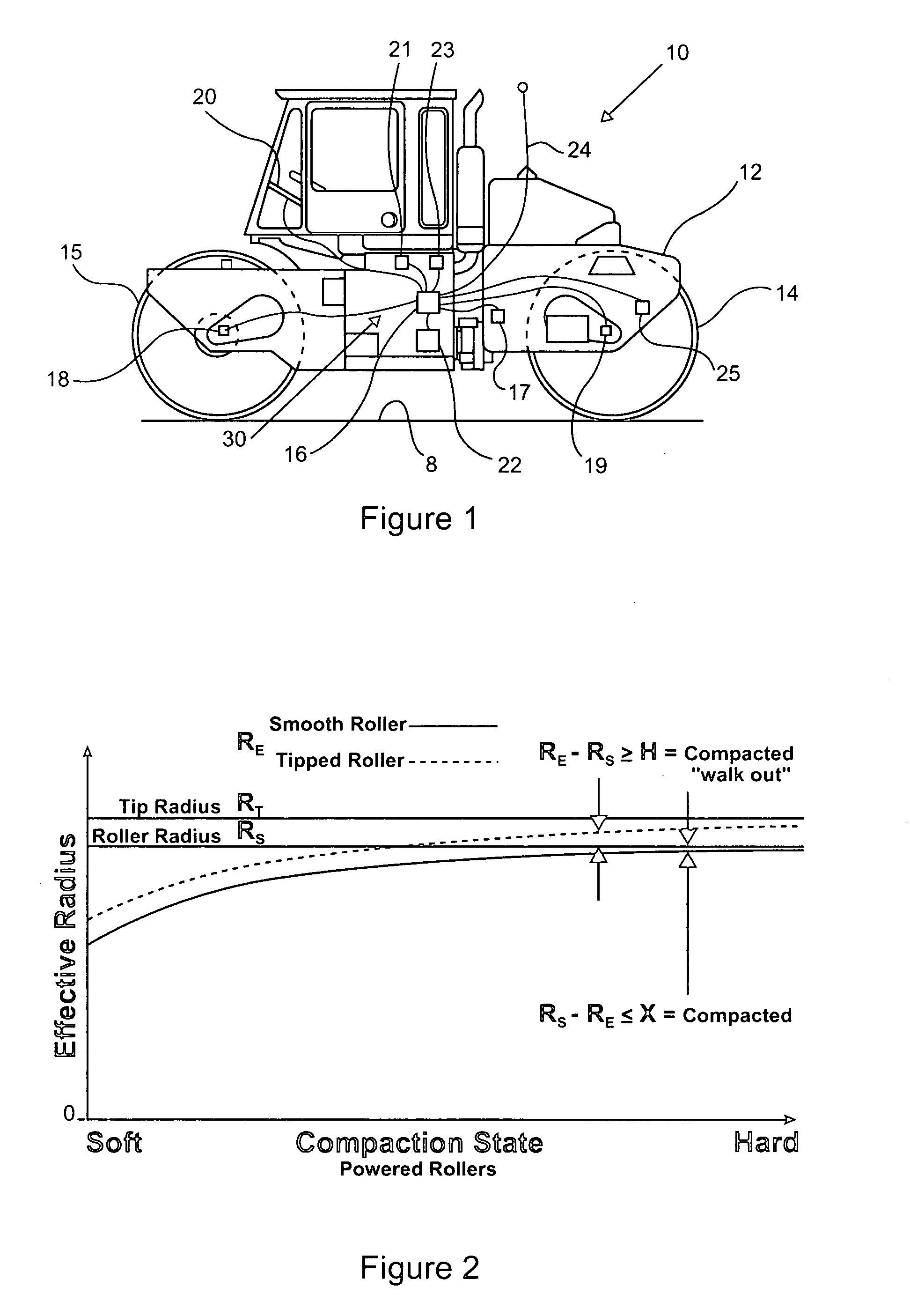
[0019]Referring to FIG. 1, a compactor 10 includes a pair of rollers 14 and 15 that are rotatably attached to a chassis 12. Although compactor 10 is self propelled, the present invention finds potential application to towed compacting rollers as well. In addition, although rollers 14 and 15 are shown as smooth for an application such as asphalt, the present invention also finds potential application to tipped rollers used in applications such as compacting waste in a landfill or compacting soil for other earthworks construction. Compactor 10 includes an onboard computer 16 that can receive signals from various inputs including sensors 17–19, 21, 23, and 25 and a position data receiver 24. Computer 16 includes a compaction algorithm that processes the sensor data to determine a compaction state of the base material 8, preferably in real time as compactor 10 is moving over the base material. This compaction data can then be stored in data storage device 22 and / or displayed to an opera...


PUM

PropertyMeasurementUnit
densityaaaaaaaaaa
roller radiusaaaaaaaaaa
energyaaaaaaaaaa

Abstract

In most construction processes, some quality assurance compaction test must be performed on a base material before further construction can take place on or relative to the compacted base material. In order to avoid costly downtime associated with waiting for a quality assurance test to be performed, the present invention contemplates generating compaction quality assurance data using on-board generated compaction quality control data. The quality control compaction data is based upon quantifying a sinkage deformation interaction between the compactor and the base material. The interaction might include monitoring an effective roller radius of the compactor, or an amount of energy transferred or consumed when the compactor moves over the base material, or even measuring a rut depth caused by the compactor. The compaction quality assurance data can be indicative of a proof rolling test result, a walk out test result, a penetrometer test result, a base material density test result, or possibly even a compactor sinkage into the base material.

Description

TECHNICAL FIELD[0001]This invention relates generally to assuring quality compaction of a base material, and more particularly to an on-board determination of compaction quality based upon a sinkage deformation interaction between the compactor and the base material.BACKGROUND[0002]Achieving soil, asphalt, waste, and other earthen material compaction requirements is critical to earthwork constructions including road beds, pavements, foundations, dams, runways, landfill liners, etc. Compaction is required most often to improve the load bearing capacity of earthen materials, improve their strength and resistance to failure, and / or improve permeability. In most instances, some secondary measurement of compaction quality is necessary in order to proceed to a next stage in construction after a base material has been compacted. In other words, the construction project must be delayed until a compaction quality assurance test is performed and passed.[0003]In the past, many different qualit...

Claims


Application Information

Patent Timeline
Patent Type & Authority Patents(United States)
IPC IPC(8): E01C19/23E02D3/02E02D3/026G01B21/16G01N3/00G01N3/02G01N9/36G01N33/42
CPCE02D3/026G01N3/00G01N9/36G01N33/42G01N2203/0085G01N2203/0244
Inventor CORCORAN, PAUL T.
Owner CATERPILLAR INC
Learn More