
Computer-assisted pull flow production management method

a production management and computer-aided technology, applied in the field of computer-aided production management, can solve problems such as the inability to automate the transmission of orders to the supplier

Inactive Publication Date: 2005-11-29
CALVASOFT BV
View PDF6 Cites 7 Cited by
  • Summary
  • Abstract
  • Description
  • Claims
  • Application Information

AI Technical Summary

Benefits of technology

"This patent is about a computer-aided method for managing the production of a finished product. It involves creating a table with information about the links between the finished product and its components, as well as parameters for each component. The method also includes creating a calendar of requirements for the finished product over a period of time. Each component is associated with a counter, which keeps track of the number of components in circulation, the total number of components after the last calculation, the number of components available in stock, and the number of components that are in the process of manufacture or ordering. The technical effect of this patent is to provide a more efficient and organized way of managing the production of a finished product."

Problems solved by technology

The principal drawbacks of this system are: it is a manual system incapable of monitoring the number of labels in circulation and of signaling possible losses of labels; it is a rigid system because the number of labels is not recalculated as a function of real and instantaneous demand; transmission of orders to the supplier is not automated and, therefore, not guaranteed; and in the case of use in internal flows (internal clients and suppliers), the emission of the resupplying order does not modify the calculation of the work charges.
A great risk is that this reconstitution of consumption which does not take into account the fluctuation of future demand can generate stocks that no longer correspond to the demand.

Method used


Image

  • Computer-assisted pull flow production management method
  • Computer-assisted pull flow production management method
  • Computer-assisted pull flow production management method

Examples


example

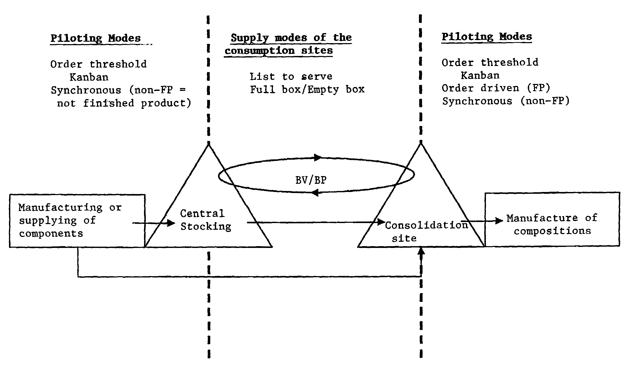
[0054]Better comprehension of the invention will be obtained from the description below which refers to a nonlimitative example of implementation.

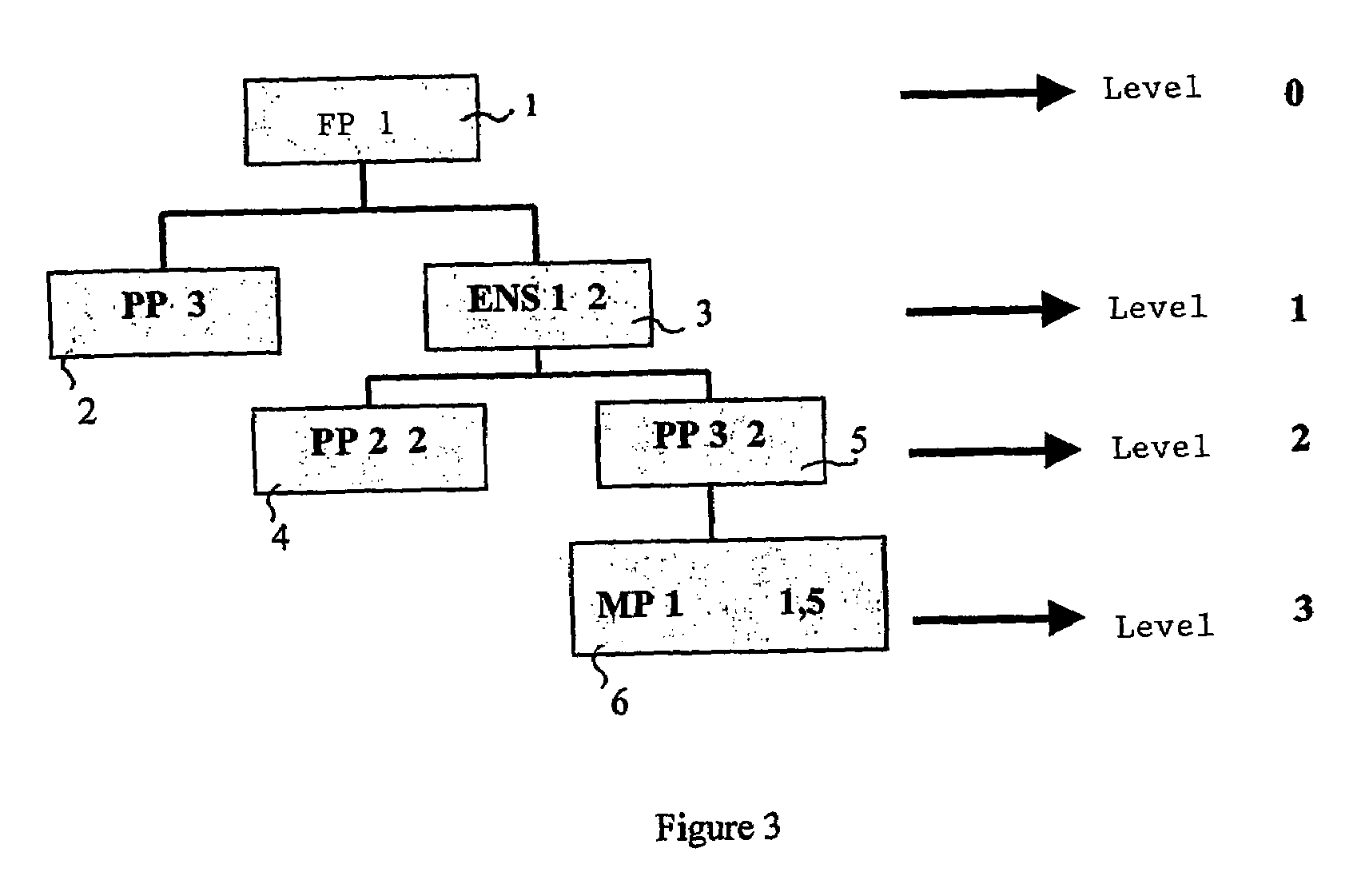
[0055]The use of a system according to the invention comprises a first step of construction of nomenclature in the form of a numerical table comprising information relative to links between a given final product and components making up the finished product. FIG. 3 represents the organizational chart of a finished product FP 1 (1). It is composed of two ENS1 components (3) and three PP components (2) corresponding to the products produced at the upstream level (level 1). The ENS component (3) is itself composed of two PP2 components (4) and of two PP3 components (5). These two types of components (4, 5) are produced at the following upstream level (level 2). The component PP3 (5) is composed of 1.5 components MP1 (6) from the following level (level 3). In summary, the finished product FP is composed of five components PP, ENS1, PP2, PP3, M...


PUM


Abstract

A method for computer-aided pulled-flow production management including constructing a nomenclature as a numerical table including information relative to links between a finished product and components composing the finished product, constructing a numerical table pertaining to parameters of each of the components, and determining the number of product requirements including constructing a numerical table of calendar requirements over a period of time, wherein each component for the components whose descriptor has a kanban step is associated with a numerical table including counter descriptors counter C0 in which is recorded a state of a number of kanban in circulation with a preceding calculation of requirements, counter C1 in which is recorded a state of a total number of kanban after a last calculation of the requirements, counter C2 in which is recorded a state of a number of kanban available in stock, pending counter C3 in which is recorded a state of a number of pending kanban and not transmitted to counter C4, and counter C4 in which is recorded a state of a number of kanban in the process of manufacture or in the process of ordering.

Description

RELATED APPLICATION[0001]This is a continuation of International Application No. PCT / FR02 / 02953, with an international filing date of Aug. 28, 2002 (WO 03 / 019435, published Mar. 6, 2003), which is based on French Patent Application No. 01 / 11181, filed Aug. 28, 2001.FIELD OF THE INVENTION[0002]This invention relates to computer-aided production management (CAPM). This invention more particularly relates to a CAPM method and system for pulled-flow production management.BACKGROUND[0003]U.S. Pat. No. 5,193,065 is known in the state of the art. This patent describes a system for ordering and distributing materials in a manufacturing environment. A manufacturing station stores and uses the material and produces a first signal of material shortage in response to consumption of a predetermined quantity of material normally found at a manufacturing station. An intelligent stocking unit stocks the material. A computer system receives the first material shortage signal and responds by searchin...

Claims


Application Information

Patent Timeline
Patent Type & Authority Patents(United States)
IPC IPC(8): G05B19/418G06Q10/00
CPCG06Q10/06G06Q50/04
Inventor LEVIONNOIS, JEAN-PIERRE
Owner CALVASOFT BV
Learn More