
Image display method and apparatus for rearview system

a rearview camera and image display technology, applied in the field of rearview cameras, can solve the problems of difficult to couple a hitch with a trailer, difficult for a driver to accurately back the vehicle, and requires a considerable skill for a driver alon

Active Publication Date: 2005-11-29
PANASONIC CORP
View PDF11 Cites 108 Cited by
  • Summary
  • Abstract
  • Description
  • Claims
  • Application Information

AI Technical Summary

Benefits of technology

[0005]The object of the invention is to provide an image display method and apparatus for a rearview camera wherein a driver alone can easily back a vehicle to connect a trailer with the vehicle.
[0006]The aforementioned object is attained by providing an image display method for a rearview camera for displaying an image shot by a rearview camera mounted on a vehicle on a screen that can be viewed from a driver's seat, wherein the method superimposes an auxiliary line image indicating the straight rear direction of the vehicle on the image shot by the vehicle on the screen. With this configuration, the driver can easily back the vehicle straight backward while watching the screen display.
[0007]Preferably, the auxiliary line image extends from the position of the hitch attached at the rear of the vehicle and the auxiliary line image has a distance marker. With this configuration, the driver can recognize the distance to the hitch thus allowing more precise operation.

Problems solved by technology

It is quite difficult for a driver to accurately back the vehicle so that the hitch mounted in a blind spot from the driver may engage the coupling member on the trailer.
When the driver is alone, it is difficult to couple a hitch with a trailer.
Thus, it requires a considerable skill for a driver alone to accurately back the vehicle and perform coupling work while watching the image from the rearview camera.

Method used


Image

  • Image display method and apparatus for rearview system
  • Image display method and apparatus for rearview system
  • Image display method and apparatus for rearview system

Examples


Embodiment Construction

[0033]One embodiment of the invention will be described referring to drawings.

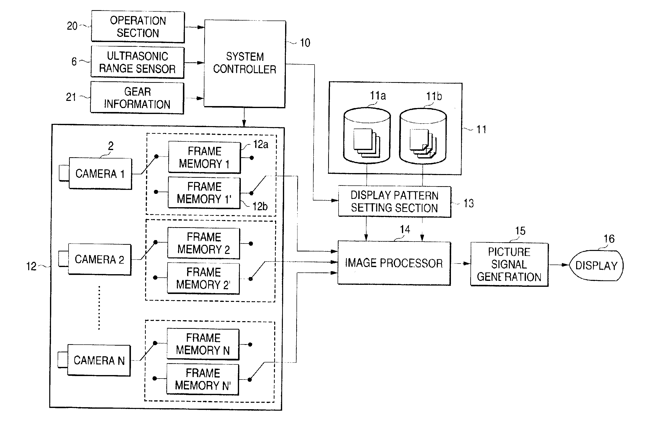
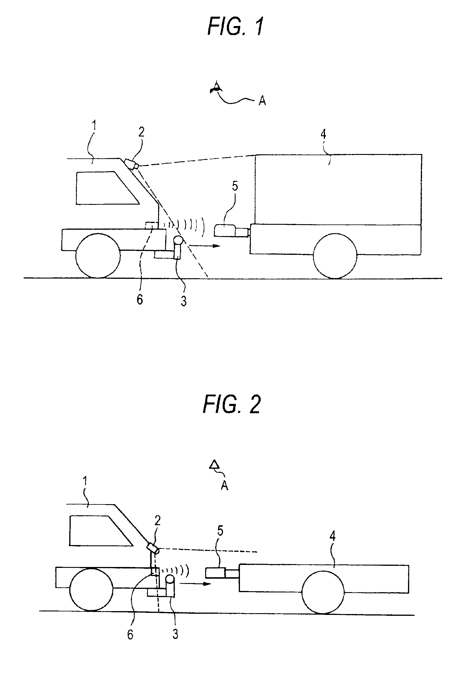
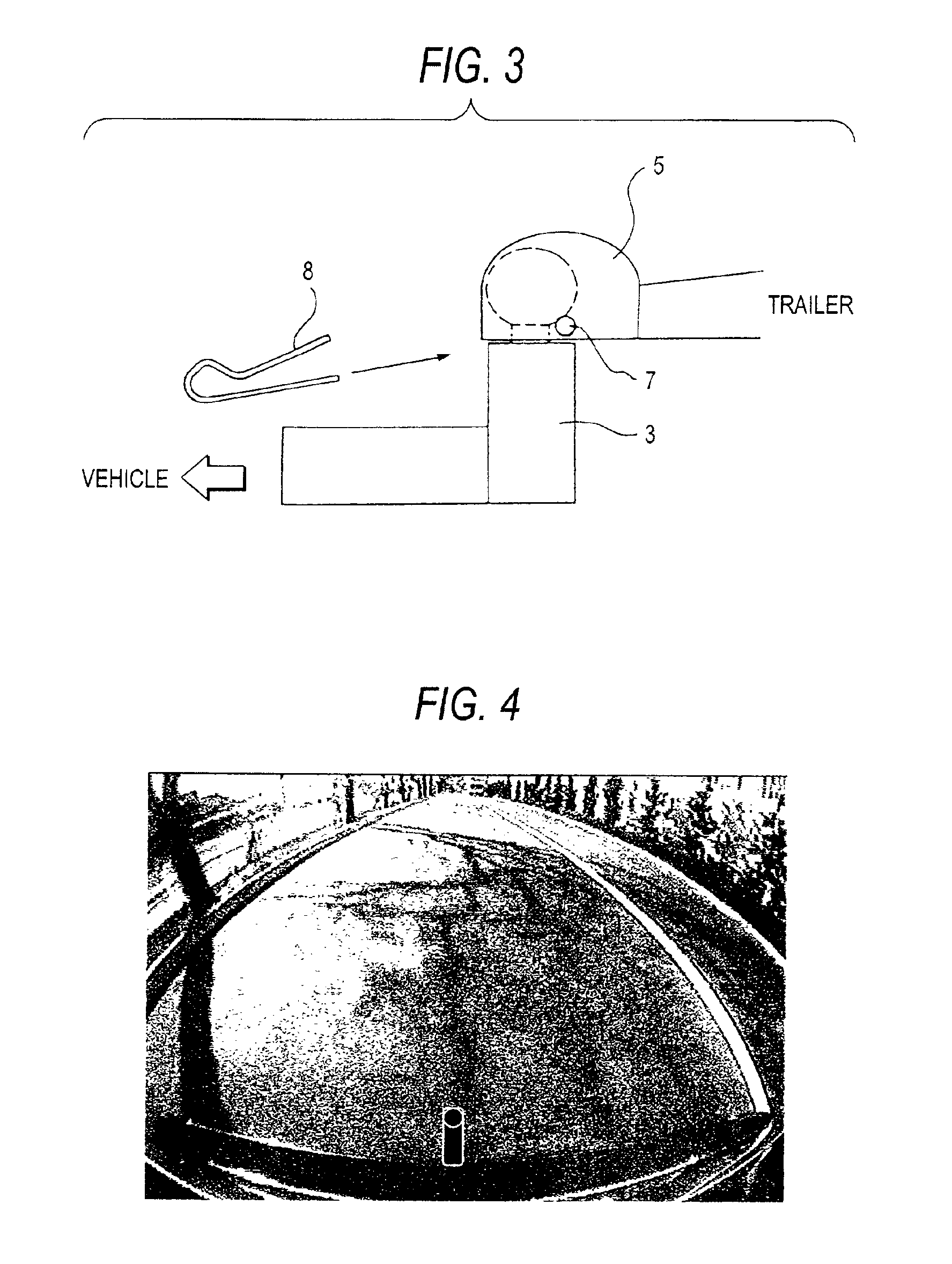
[0034]FIG. 1 shows a relation between a vehicle mounting a rearview camera and a hitch and a trailer. A rearview camera 2 is mounted at the rear of the vehicle 1. One rearview camera may be provided at the rear of the vehicle or two rearview cameras may be provided and images shot by two cameras maybe synthesized to form an image displayed on the screen at the driver's seat. A hitch 3 is fixed at the center of the rear of the vehicle. The vehicle is backed and the hitch 3 engages a coupling member 5 on a trailer 4. An ultrasonic range sensor 6 is attached at the rear of the vehicle so allow measurement of the distance to a rearward obstacle.

[0035]The example in FIG. 1 shows a case where the mounting position of the rearview camera 2 is restricted so that it is impossible to capture an image of the hitch 3 in the shooting angle of the rearview camera 2. In this case, as an image of the hitch 3 displayed on ...


PUM


Abstract

An image display method for a rearview camera for displaying an image shot by a rearview camera mounted on a vehicle on a screen that can be viewed from a driver's seat, the method includes the step of displaying an auxiliary line image indicating the straight rear direction of the vehicle superimposed on the image shot by the vehicle on the screen. When the vehicle has approached the trailer within a predetermined range, an image from the rearview camera is converted to an image from a virtual overhead viewpoint then displayed on the screen. The driver easily back the vehicle to bring the hitch in the blind spot at the rear of the vehicle to coincide with a coupling member on the trailer while watching the screen display.

Description

BACKGROUND OF THE INVENTION[0001]The present invention relates to an image display method and apparatus for a rearview camera mounted on a vehicle, and in particular to an image display method and apparatus for a rearview camera mounted on a vehicle for assistance of a driver when a vehicle is backed and a coupling member attached at the rear of the vehicle (hereinafter referred to as a “hitch”) is coupled to a trailer.[0002]A vehicle, that mounts apparatus where a rearview camera is attached to the rear of the vehicle and an image from the rearview camera is displayed on a car navigation screen at the driver's seat for the purpose of safety check, has recently been in wide use. A wide angle camera is used as a rearview camera in order to avoid collision with an rearward obstacle when a vehicle is backed for parking. A wide range is accommodated in a single screen.[0003]Some vehicles have a hitch at the rear of the vehicle in order to couple a trailer or a camper to the back, when a...

Claims


Application Information

Patent Timeline
IPC IPC(8): G03B15/00B60R1/00B60R21/00H04N7/18
CPCB60R1/00B60R1/003G06T5/006H04N7/183B60R2300/808B60D1/36B60D1/62G06T5/80B60R1/26B60R1/28H04N7/18
Inventor HIRAMA, YUICHIMASUDA, SATORUMIMURA, HIDETOSHIMIYAMA, KAZUKITAKATA, MASAHIRO
Owner PANASONIC CORP
Learn More