
System and process for viewing and navigating through an interactive video tour

a video tour and interactive technology, applied in the field of video tours, can solve the problems of inability to capture visual effects, scene look real, and none have been able to provide a viewer with continuous control over both position and viewpoint, and achieve the effect of unprecedented presen

Active Publication Date: 2005-11-29
MICROSOFT TECH LICENSING LLC
View PDF1 Cites 51 Cited by
  • Summary
  • Abstract
  • Description
  • Claims
  • Application Information

AI Technical Summary

Benefits of technology

[0008]The present invention is directed toward a system and process for providing an interactive video tour of a tour site to a user. In general, the present system and process provides an image-based rendering system that enables users to explore remote real world locations, such as a house or a garden. While many previous systems have been based on still photography and / or 3D scene modeling, the present approach is based directly on filming an environment, and then using image-based rendering techniques (rather than 3D reconstruction, which may be brittle) to replay the tour in an interactive manner. As such, the resulting experience is referred to as Interactive Video Tours. The experience is interactive in that the user can move freely along a path, choose between different paths at branch points, and look around in any direction. The user experience is additionally enhanced with multimedia elements such as overview maps, video textures, and sound. The combination of high resolution continuous imagery combined with interactivity provides viewers with an unprecedented sense of presence.
[0015]The video data may be compressed to facilitate its storage and transmission. If it is, it needs to be decompressed before being processed as described above. The video data is compressed using a compression method which allows the efficient decompression of any frame, not just the next sequential frame. In addition the compression scheme allows any portion of a frame to be decompressed without having to decompress the rest of the frame. In this way only the portion of the frame that is being rendered to produce the current tour image needs to be decompressed, thereby reducing the processing needed and the time required to display the next image to the user.
[0019]In addition, the viewing and navigation window can include a map sector that displays a map graphic of the tour site. This map graphic can include a line representing the tour path on the map graphic, as well as an indicator (e.g., an arrow) that identifies the point on the tour path from which the user is currently viewing the tour site. These items are obtained for display in the viewing and navigation window from the scene data. For example, a map region table in the scene data provides the particular map graphic that is to be displayed for each of a prescribed set of frame ranges. This allows the map to be customized for each region such as highlighting the region the user is currently viewing. A path table can be included to identify the location on the map graphic representing the point on the tour path that each frame (including the current one) was captured, thereby facilitating the placement of the indicator on the map graphic. The indicator can also be configured to point in the user-specified direction of motion along the path. Still further, as indicated previously, the user can select a point on the tour path line of the map graphic and as a result the next frame processed corresponds to the user-selected path point. Thus, the user can jump to another part of the tour site without having to follow the path.

Problems solved by technology

While these systems allow the viewer to have unrestricted motion throughout the digitized scene, they fail to capture the visual effects such as reflections in windows, specularities, and finely detailed geometry such as foliage, that make the scene look real.
However, to date none have been able to provide a viewer with continuous control over both position and viewpoint, as would be desirable to achieve the goal of creating a sense of being there.
In addition, these systems cannot achieve a fully interactive, photorealistic, video based tour on a personal computer at or above broadcast video resolutions and frame rates.

Method used


Image

  • System and process for viewing and navigating through an interactive video tour
  • System and process for viewing and navigating through an interactive video tour
  • System and process for viewing and navigating through an interactive video tour

Examples


Embodiment Construction

[0031]In the following description of the preferred embodiments of the present invention, reference is made to the accompanying drawings which form a part hereof, and in which is shown by way of illustration specific embodiments in which the invention may be practiced. It is understood that other embodiments may be utilized and structural changes may be made without departing from the scope of the present invention.

1.0 The Computing Environment

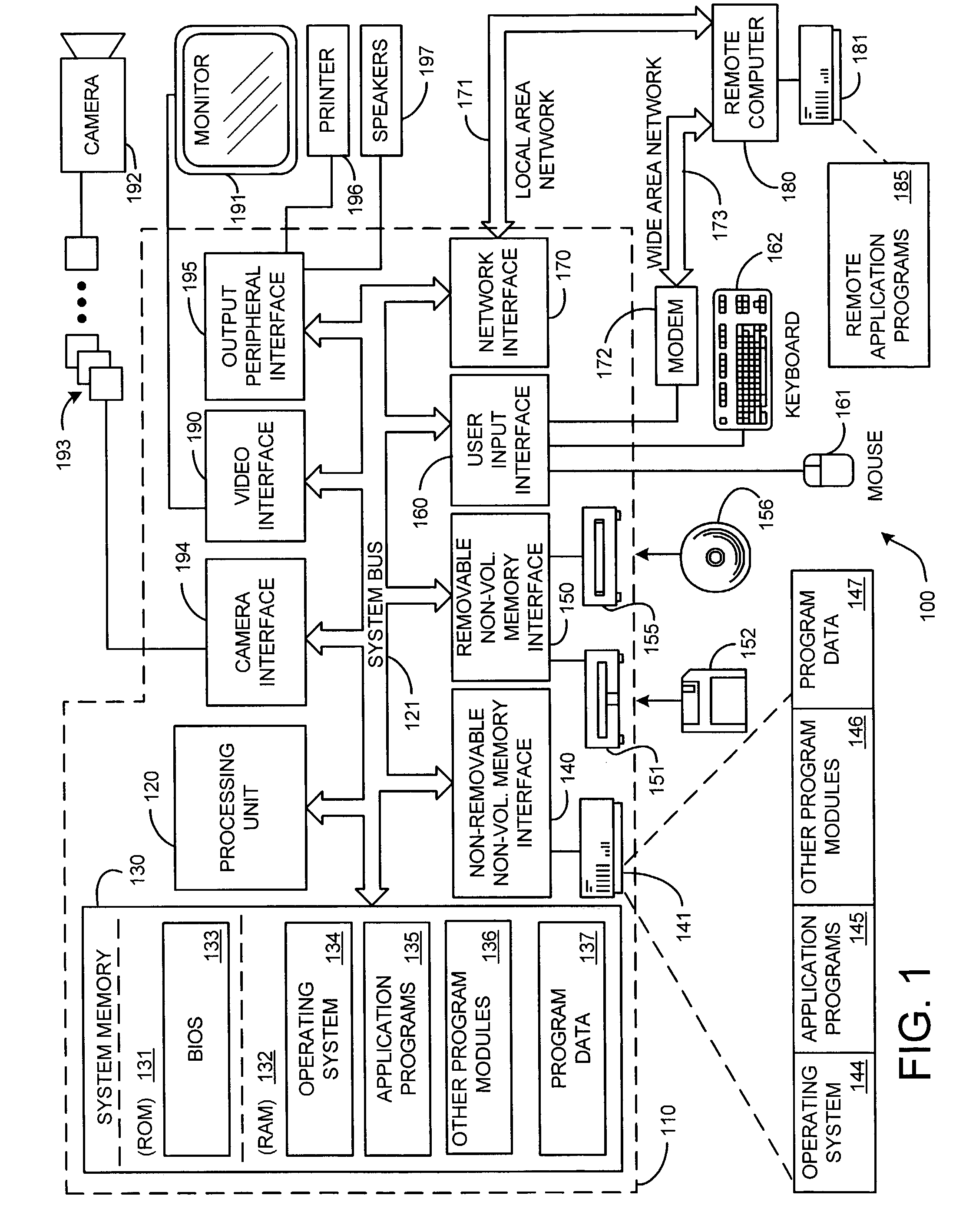
[0032]Before providing a description of the preferred embodiments of the present invention, a brief, general description of a suitable computing environment in which the invention may be implemented will be described. FIG. 1 illustrates an example of a suitable computing system environment 100. The computing system environment 100 is only one example of a suitable computing environment and is not intended to suggest any limitation as to the scope of use or functionality of the invention. Neither should the computing environment 100 be interpre...


PUM


Abstract

A system and process for providing an interactive video tour of a tour site to a user is presented. In general, the system and process provides an image-based rendering system that enables users to explore remote real world locations, such as a house or a garden. The present approach is based directly on filming an environment, and then using image-based rendering techniques to replay the tour in an interactive manner. As such, the resulting experience is referred to as Interactive Video Tours. The experience is interactive in that the user can move freely along a path, choose between different directions of motion at branch points in the path, and look around in any direction. The user experience is additionally enhanced with multimedia elements such as overview maps, video textures, and sound.

Description

BACKGROUND[0001]1. Technical Field[0002]The invention is related to video tours, and more particularly to a system and process for providing an interactive video tour of a tour site using an image-based rendering technique that enables users to explore remote real world locations.[0003]2. Background Art[0004]Interactive scene walkthroughs have long been an important application area of computer graphics, as evidenced by the efficient rendering algorithms that have been developed for visualizing large architectural databases [9,1]. In fact, many beautiful examples of 3D reconstruction from multiple images, video, and / or range data have been demonstrated by research groups around the world. The most ambitious of these is Seth Teller's City Scanning Project at MIT [2], in which dozens of buildings have been reconstructed from high-resolution, high dynamic range omnidirectional panoramas. While these systems allow the viewer to have unrestricted motion throughout the digitized scene, th...

Claims


Application Information

Patent Timeline
Patent Type & Authority Patents(United States)
IPC IPC(8): G06F17/00G06F17/30G07F11/00G09G5/00
CPCG06F17/30056G06F17/30855G06F16/4393G06F16/748
Inventor UYTTENDAELE, MATTHEW T.KANG, SING BINGSZELISKI, RICHARDCRIMINISI, ANTONIO
Owner MICROSOFT TECH LICENSING LLC
Learn More