
Valve with seat assembly

a seat and valve technology, applied in the field of valves, can solve the problems of surface imperfections, high temperature and pressure, and the inability of the surface to tolerate imperfections, and achieve the effect of higher temperatures and pressur

Inactive Publication Date: 2005-11-22
WORLDWIDE OILFIELD MACHINE INC
View PDF22 Cites 86 Cited by
  • Summary
  • Abstract
  • Description
  • Claims
  • Application Information

AI Technical Summary

Benefits of technology

The present invention provides an improved seat assembly for a gate valve that can operate at higher temperatures and pressures. The seat assembly includes a unidirectional seal assembly and a de-energizing means. The seat assembly also includes a pocket surrounding the inlet and outlet passages adjacent to the closure member chamber, and a telescoping seat assembly in each of the recesses. The telescoping seat assemblies comprise an outer seat element for sealing within the pocket of the valve body and an inner seat element for sealing engagement with the closure member. The de-energizing seal assembly is adjacent to the pocket of the valve body and can effect a seal by moving the seal into engagement with the pocket of the valve body or permitting leakage past the seal. The valve may further comprise one or more slots in the outer seat element and a seal ring mounted between the pair of oppositely oriented unidirectional seals.

Problems solved by technology

However, such seals do not create a reliable seal as easily as elastomeric O-rings.
The tolerances must be much tighter and the surfaces cannot tolerate imperfections.

Method used


Image

  • Valve with seat assembly
  • Valve with seat assembly
  • Valve with seat assembly

Examples


Embodiment Construction

[0047]In one embodiment of the present invention, an objective is successfully reached for providing a gate valve operable to control a wider range of fluids at wider ranges of temperature and pressure and to de-energize the seals under a wide variety of conditions when the valve is cycled during operation. The gate valve of the present invention also discloses one or more apparatus and methods by which a secondary seal can be provided if a primary seal fails. As well, the gate valve of the present invention may be designed so that pressure lock may be eliminated in one or more ways.

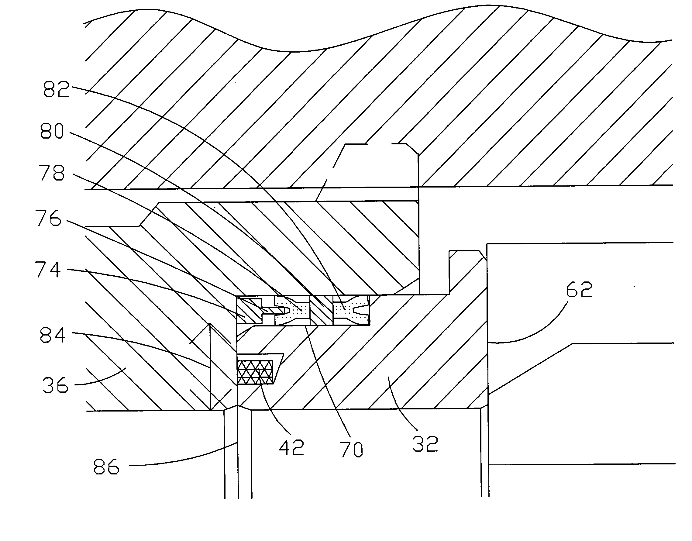
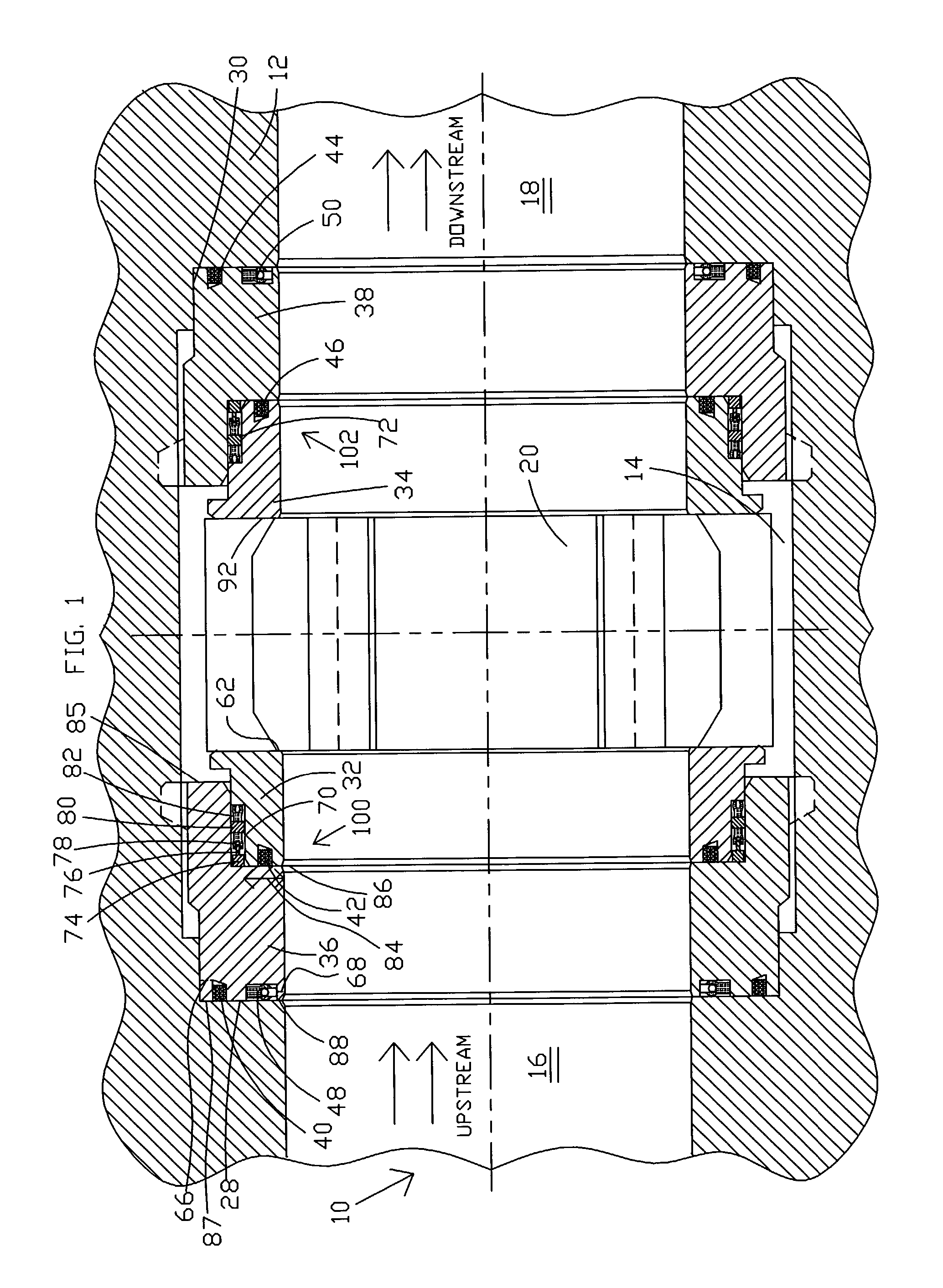
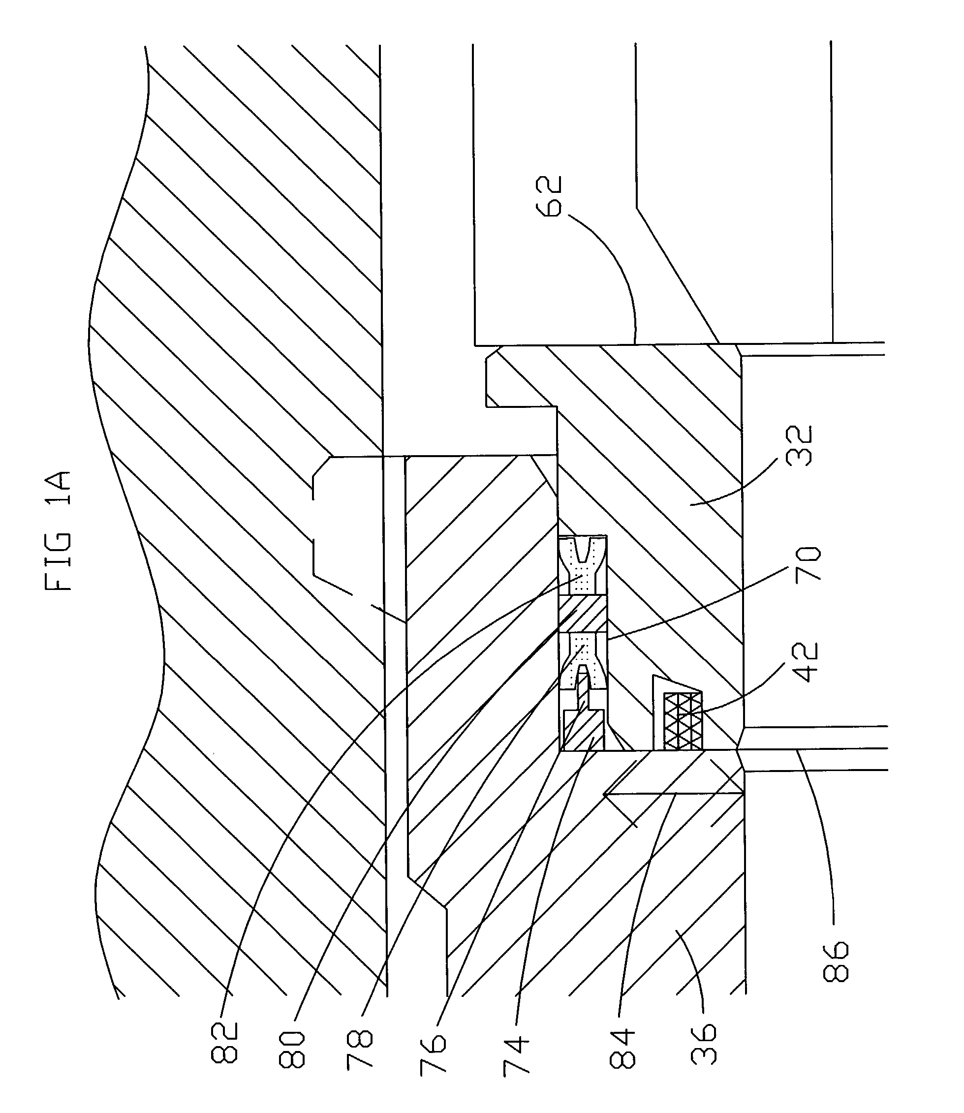
[0048]Referring now to the drawing, and more particularly to FIG. 1, where one possible preferred embodiment of gate valve 10, in accord with the present invention, is illustrated. Gate valve 10 uses two preferably mirror image sets of telescoping seat elements, such as upstream seat elements 100 and downstream seat elements 102, that have many advantages for operation with a gate valve as discussed here...


PUM


Abstract

A valve is disclosed having a telescoping seat assembly that fits into a pocket or enlargement of a flow passageway through the valve body. An outer seat element seals with the pocket utilizing a plurality of seal assemblies to seal with the pocket whereby pressure may become trapped between the seal assemblies during valve operation under certain unusual conditions. A groove with a tapering or angled surface is provided in the outer seat. A seal ring is disposed in the groove whereby pressure from one side of the seal ring moves the seal along the tapering or angled surface to wedge the seal into contact with the wall of the pocket. Pressure from the other side of the seal ring moves the seal ring along the tapering surface and away from the wall of the pocket so as to be out of sealing engagement thereby permitting bleeding off of the pressure or de-energizing of the seal assemblies.

Description

BACKGROUND OF THE INVENTION[0001]Benefit is hereby claimed of U.S. Provisional Application No. 60 / 453,536 filed on Mar. 11, 2003.[0002]1. Field of the Invention[0003]The present invention relates generally to valves and, more particularly, to apparatus and methods for a valve telescoping seat assembly.[0004]2. Description of the Background[0005]Telescoping seat assemblies have been known for use in gate valves for some time. One advantage of this type of seat assembly is the ability to provide a force on the seats and valve body that varies due to pressures encountered. In this way, one is assured of a good seal with a wide range of pressures. Another advantage of one exemplary type of telescoping seat assembly is the ability to provide both an upstream and a downstream seal. This provides two working seals that thereby increase the reliability of operation as compared with most other valves that utilize only one seal, such as a downstream seal. Another advantage is that friction du...

Claims


Application Information

Patent Timeline
Patent Type & Authority Patents(United States)
IPC IPC(8): F16K3/02F16K3/20
CPCF16K3/0227F16K3/207
Inventor SUNDARARAJAN, ALAGARSAMY
Owner WORLDWIDE OILFIELD MACHINE INC
Learn More