
Explosive pipe severing tool

Inactive Publication Date: 2005-11-01
HUNTING TITAN
View PDF22 Cites 44 Cited by
  • Summary
  • Abstract
  • Description
  • Claims
  • Application Information

AI Technical Summary

Benefits of technology

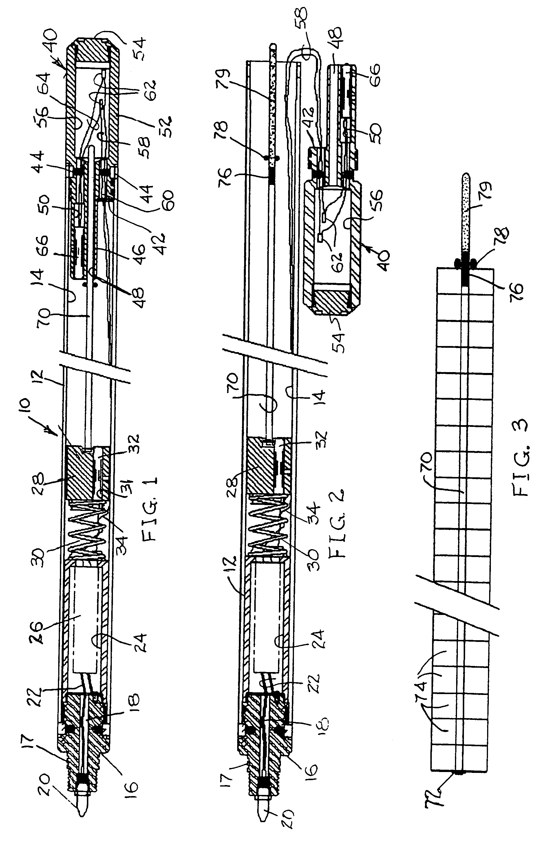
[0019]Within the upper end of the outer housing barrel is an inner tubular housing for an electronic detonation cartridge having a relatively high discharge voltage, 5,000 v or more, for example. Below the inner tubular housing is a cylindrical, upper detonator housing. The upper detonator housing is resiliently separated from the lower end of the inner tubular housing by a suitable spring. The upper detonator housing includes a receptacle socket 31 for an exploding bridge wire (EBW) detonator. The axis for the upper detonator receptacle socket is laterally offset from the outer housing barrel

Problems solved by technology

The operational circumstances of such industrial enterprise occasionally presents a driller with a catastrophe that requires him to sever his pipe string at a point deep within the wellbore.
For example, a great length of wellbore sidewall may collapse against the drill string causing it to wedge tightly in the well bore.
The drill string cannot be pulled from the well bore and in many cases, cannot even be rotated.
However, if fuse length is not accurate or problems exist in the booster / detonator connections, the collision may not be realized at all and the device will operate as a “non-colliding” tool with substantially reduced severing pressures.
The reliability of state-of-the-art severing tools is further compromised by complex assembly and arming procedures required at the well site.
Complete assembly must then take place at the well site under often unfavorable working conditions.
Finally, the electric detonators utilized by state-of-the-art severing tools are not as safe from the electric stray currents and RF energy points of view, further complicating the safety procedures that must be observed at the well site.

Method used


Image

  • Explosive pipe severing tool
  • Explosive pipe severing tool
  • Explosive pipe severing tool

Examples


Embodiment Construction

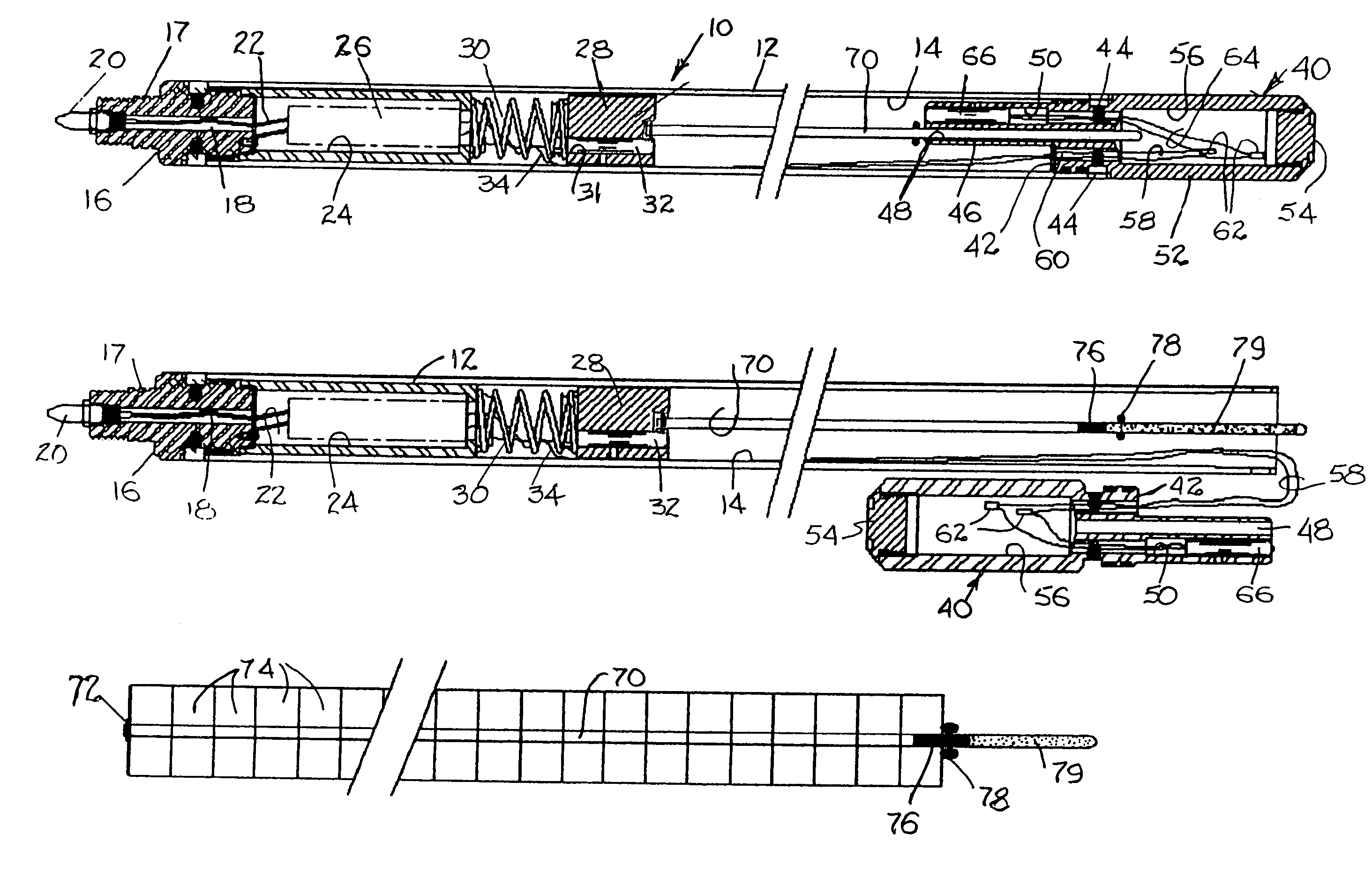
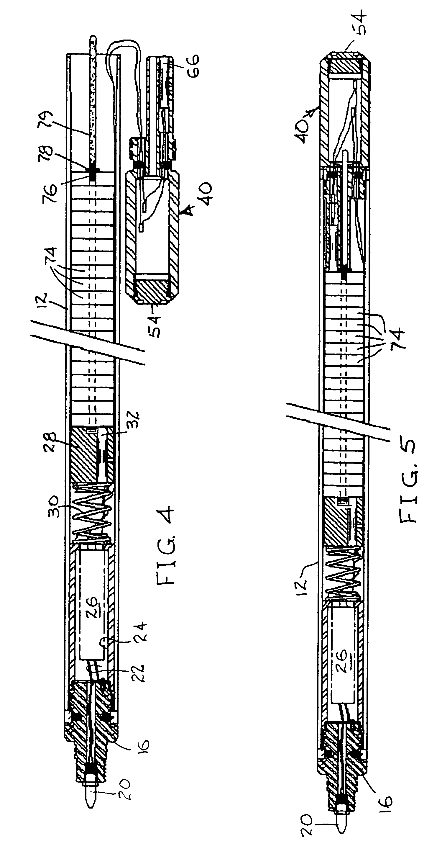
[0030]Referring to the FIG. 1 cross-sectional view of the invention 10, a tubular outer housing 12 having an internal bore 14 is sealed at an upper end by a plug 16. The plug 16 includes an axial bore 18 and an electrical connector 20 for routing detonation signal leads 22. A boss 17, projecting from the base of the plug, is externally threaded for the attachment of the desired suspension string such as an electrical wireline or service tubing.

[0031]An inner housing tube 24 is secured to and extends from the upper end plug 16 into the internal bore 14 of the outer housing 12. The inner housing tube 24 encloses a capacitive firing cartridge 26. Below the inner housing 24 is an upper detonator housing 28. A coil spring 30 links the upper detonator housing 28 to the inner housing tube 24. An exploding bridge wire (EBW) detonator or exploding foil initiator (EFI) 32 is seated within a receptacle socket formed in the upper detonator housing 28 laterally of the housing axis. Electrical co...


PUM


Abstract

A pipe severing tool is arranged to align a plurality of high explosive pellets along a unitizing support structure whereby all explosive pellets are inserted within or extracted from a tubular housing as a singular unit. Electrically initiated exploding wire detonators (EBW) are positioned at opposite ends of the tubular housing for simultaneous detonation by a capacitive firing device. The housing assembly includes a detachable bottom nose that permits the tool to be armed and disarmed without disconnecting the detonation circuitry. Because the tool is not sensitive to stray electrical fields, it may be transported, loaded and unloaded with the EBW detonators in place and connected.

Description

CROSS REFERENCE TO RELATED APPLICATIONS[0001]This application is a Division of application Ser. No. 09 / 949,990 Filed Sep. 10, 2001 now abandoned.STATEMENT REGARDING FEDERALLY SPONSORED RESEARCH OR DEVELOPMENT[0002]Not ApplicableBACKGROUND OF THE INVENTION[0003]1. Field of the Invention[0004]The present invention relates to the earthboring arts. More particularly, the invention relates to methods and devices for severing drill pipe, casing and other massive tubular structures by the remote detonation of an explosive cutting charge.[0005]2. Description of Related Art[0006]Deep well earthboring for gas, crude petroleum, minerals and even water or steam requires tubes of massive size and wall thickness. Tubular drill strings may be suspended into a borehole that penetrates the earth's crust several miles beneath the drilling platform at the earth's surface. To further complicate matters, the borehole may be turned to a more horizontal course to follow a stratification plane.[0007]The op...

Claims


Application Information

Patent Timeline
IPC IPC(8): E21B31/00E21B29/02F42B3/00F42B3/24F42B3/26F42D1/22F42D3/00
CPCE21B29/02F42B3/00F42B3/24F42B3/26F42D1/22F42D3/00E21B17/06
Inventor BELL, WILLIAM T.
Owner HUNTING TITAN
Learn More