
Rod for cervical vertebra and connecting system thereof

a technology for connecting systems and rods, which is applied in the field of rod plates for cervical vertebrae, can solve the problems of difficult manufacturing, difficult to set connectors, and difficult to align the longitudinal direction of rod-shaped mounting portions with the supporting and fixing devices

Inactive Publication Date: 2005-10-25
SHOWA IKA KOHGYO
View PDF23 Cites 159 Cited by
  • Summary
  • Abstract
  • Description
  • Claims
  • Application Information

AI Technical Summary

Problems solved by technology

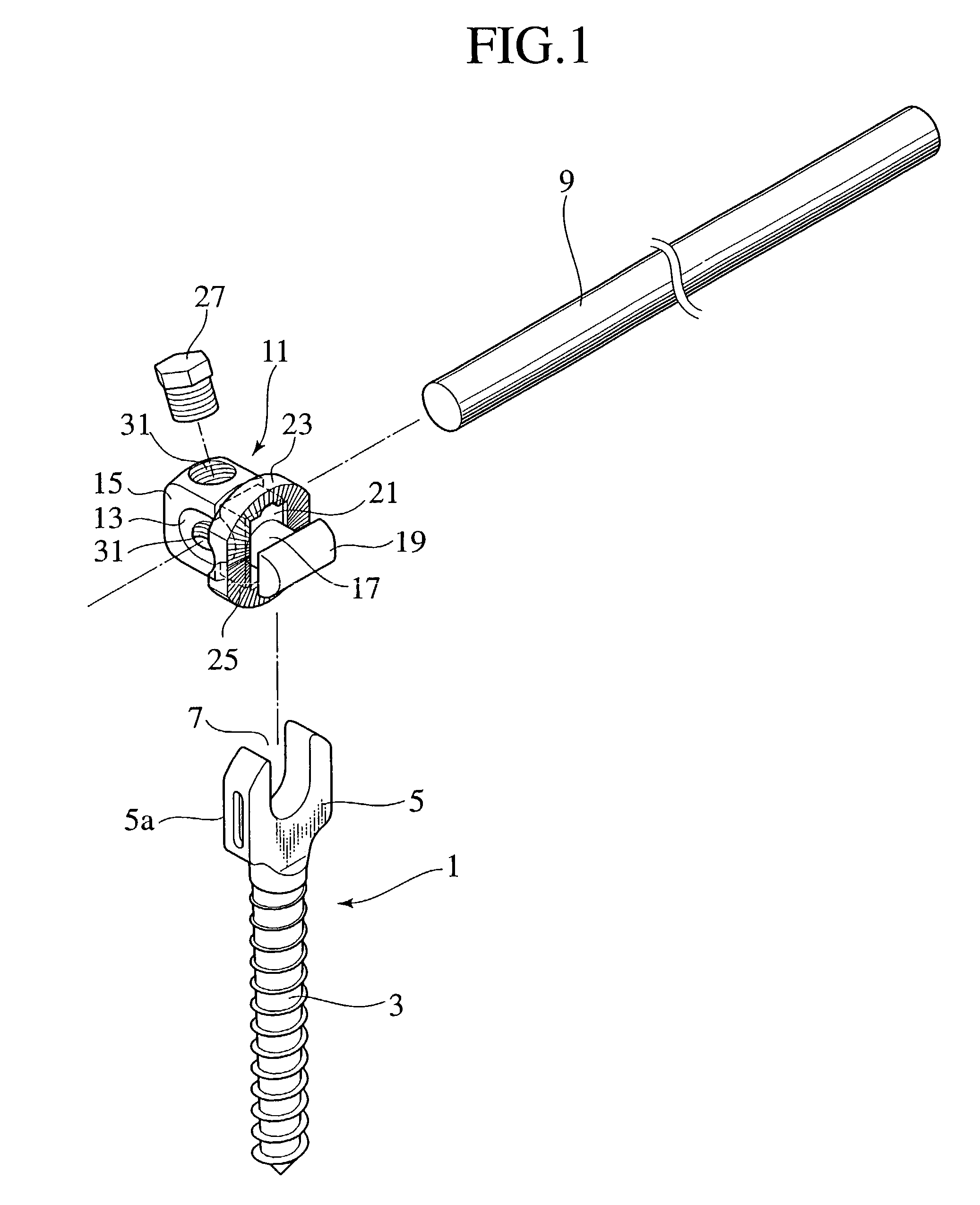
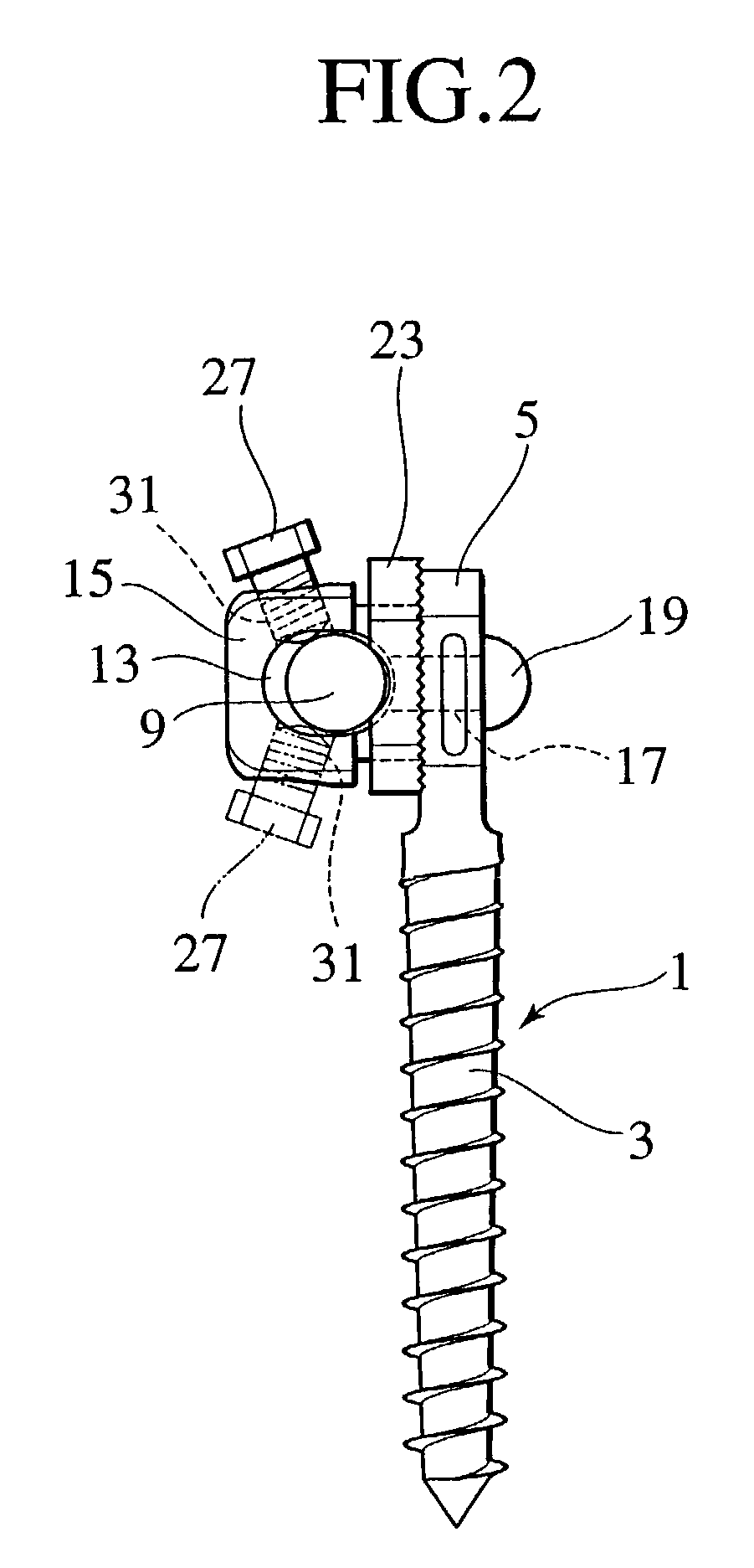
In the connector structure as described above, since the structure is made such as to press the lock member 23 via the rod 9, it is impossible to stably mount the connector main body 15 to the implant 1 in a state that the rod 9 is not inserted to the through hole 13 of the connector main body 15, so that there is a problem that it is hard to set the connector.
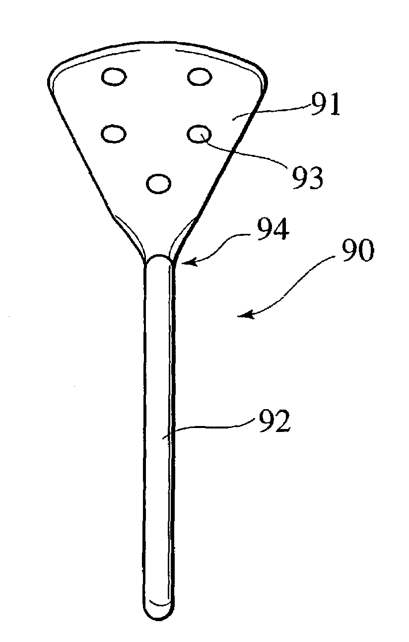
Moreover, in the structure of the rod plate connected to the connector described above, since the shapes are different between right and left, it is necessary to properly use the right and left parts and it is necessary to independently manufacture them, so that it is hard to manufacture them.
Further, there is a problem that it is not easy to align the longitudinal direction of the rod-shaped mounting portion with the supporting and fixing device.

Method used


Image

  • Rod for cervical vertebra and connecting system thereof
  • Rod for cervical vertebra and connecting system thereof
  • Rod for cervical vertebra and connecting system thereof

Examples


Embodiment Construction

[0033]Hereinafter, embodiments according to the present invention will be described with reference to FIGS. 4A to 8.

“CONNECTOR”

[0034]With reference to FIG. 4A, an implant 41 screwed and inserted to a body of vertebra of a vertebral bone is formed in a pipe shape provided with a through hole in an axial core portion, a cylindrical portion 45 is provided in a head portion of a screw portion 43 screwed and inserted to the body of vertebra of the vertebral bone, and a polygonal tool engagement portion 47 is formed in a top portion of the cylindrical portion 45.

[0035]A connector 51 for connecting a bone connecting rod 49 connecting the rod portion in another end side of the cervical vertebra rod plate, for example, fixing one end portion to the cranium or between the vertebral bone and the vertebral bone, to the implant 41 is provided with a main body for an implant 55 having an engagement hole 53 freely engaged with the circular portion 45 of the head portion in the implant 41, and a fa...


PUM


Abstract

A connector is provided with a first fastening member 55 having an engagement hole 53 freely engaging with a head portion of an implant 41 screwed and inserted to a body of vertebra and a fastening groove 57, a second fastening member 63 having an insertion hole 61 freely inserting a rod 49 therethrough and a fastening groove 65, and a fastening device 69 freely penetrating a through hole 59 crossing to the fastening groove 57 in the first fastening member 55 and a through hole 67 crossing to the fastening groove 65 in the second fastening member 63, and an angle adjusting and engaging portion is provided on connecting surfaces 55a and 63a between the first fastening member 55 and the second fastening member 63.

Description

CROSS-REFERENCE TO RELATED APPLICATION[0001]The present application is a divisional of U.S. application Ser. No. 09 / 955,943 filed Sep. 20, 2001, now U.S. Pat. No. 6,620,164 the disclosure of which is expressly incorporated by reference herein in its entirety.BACKGROUND OF THE INVENTION[0002]1. Field of the Invention[0003]The present invention relates to a rod plate for a cervical vertebra which connects and bonds a cranium portion and a cervical vertebra portion, and a connector for connecting them. More particularly, the present invention relates to a rod plate for a cervical vertebra which can easily mount to the cranium portion, and a connector which can set a mounting angle of the rod plate for the cervical vertebra and an implant to a desired angle.[0004]2. Description of the Related Art[0005]As a structure of a connector for a rod plate and a structure of the rod plate according to the related art, there are structures shown in FIGS. 1, 2 and 3.[0006]At first, the related art ...

Claims


Application Information

Patent Timeline
IPC IPC(8): A61B17/70A61B17/58A61B17/80
CPCA61B17/7002A61B17/7037A61B17/7038A61B17/7041A61B17/7055A61B17/7011A61B17/7049A61B17/80A61B17/58
Inventor UEYAMA, KAZUMASASANNOHE, AKIOECHIGOYA, NAOKIORIBE, KAZUYAINA, NORIYUKI
Owner SHOWA IKA KOHGYO
Learn More